Arduino Breathalyzer Using MQ3 Gas sensor and OLED Display
- Nick Koumaris
- http://educ8s.tv/
- info@educ8s.tv
- 31.113 Views
- moderate
- Tested
Introduction
Hi guys, Welcome to this tutorial. Today we will build a breathalyzer using the MQ3 gas sensor, an OLED display and Arduino.
A breathalyzer is a generalized trademarked name for devices used for determining blood alcohol content from a breath sample. This means the device can detect from your breadth, the amount of alcohol you have taken. This device becomes very useful when you consider several cases of accidents caused by drunk driving. With this device, you can easily warn the driver of a car when he/she is too drunk to drive a car. It is important to note that this project is not accurate enough to replace the standard breathalyzer and you shouldn’t drink and drive.
For this project, we will be using the MQ3 alcohol sensor. It is a cheap semiconductor sensor capable of detecting the presence of alcohol in air at concentrations between the value 0.05 mg/L to 10 mg/L. The sensor uses a chemical reaction to determine alcohol level and the primary sensing element in the sensor is SnO2, the conductivity of SnO2 is low in clean air but increases as the concentration of alcohol gas in air (breath) increases. It has high sensitivity to alcohol and has a good resistance to disturbances and noise from things like smoke and gasoline.
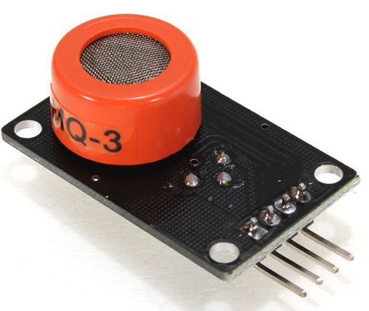
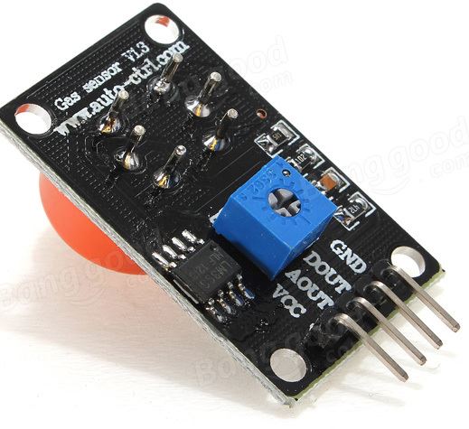
The MQ3 module has 4 pins including both digital and analog outputs, VCC and Gnd. MQ3 alcohol sensor module can be easily interfaced with microcontrollers and development boards like Arduino Boards, Raspberry Pi etc.
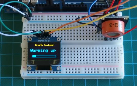
The readings from the MQ3 sensor will be displayed via the Arduino mega on an OLED display. A tutorial detailing how to use the OLED display with the arduino is available here.
The MQ3 sensor senses alcohol in a somewhat controlled environment in the sense that the sensor only senses alcohol after heating up to a particular level. To get accurate results, it needs between 10-15 mins on power up to heat up to the desired temperature level which is usually around 40 degrees.
its important to note that this sensor only detects alcohol molecules in air and not liquid alcohol.
Project Parts
To dive in, here is a list of components needed for the tutorial. These components can be purchased via the attached links.
- MQ3 Alcohol Sensor Module
- 0.96′ I2C OLED display
- Arduino Mega (Uno or any other board type would also work)
- Small Breadboard
- Jumper Wires
Schematics
Connect all the components as shown in the schematics below.
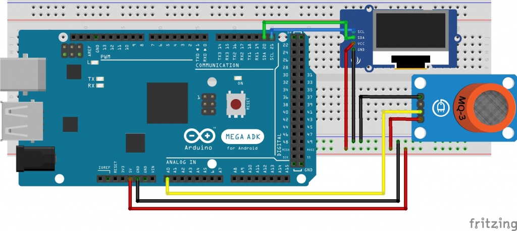
Connect the component as shown above. For clarity, the pin connections are also described below.
MQ3 – Arduino
 VCC - 5v
 GND - GND
 A0 - A0
OLED – ARDUINO
 VCC - 5v
 GND - GND
 SCL - SCL(Pin D21)
 SDA - SDA(Pin D20)
with the connections all done, we are ready to start writing the code.
Code
As usual, we will break down the code before dropping it all.
The first thing we do is include the functions which are needed for us to be able to interface the OLED display with the Arduino. more information on how the display part of this project works can be found here.
//Written by Nick Koumaris
//info@educ8s.tv
//educ8s.tv

#include <SPI.h>
#include <Wire.h>
#include <Adafruit_GFX.h>
#include <Adafruit_SSD1306.h>
We then input the wait time. Here I used 900s but you can change it to suit your needs.
int TIME_UNTIL_WARMUP = 900;
unsigned long time;
We then declare the analog pin to which our alcohol sensor is connected i.e Analog pin 0.
int analogPin = 0;
The next major part after declaring the pin is in the loop function, where we call the read alcohol function which gives us the analog value as determined by the alcohol sensor.
val = readAlcohol();
with the value stored, we then check if the device is warm and display the Analog value using the print alcohol function. We also display a message based on the analog level to say whether the owner of the breadth is sober or not.
if(time<=TIME_UNTIL_WARMUP)
 {
   time = map(time, 0, TIME_UNTIL_WARMUP, 0, 100);
   display.drawRect(10, 50, 110, 10, WHITE); //Empty Bar
   display.fillRect(10, 50, time,10,WHITE);
 }else
 {
    printTitle();
    printAlcohol(val);
    printAlcoholLevel(val);
 }
The full code for this project is available below.
//Written by Nick Koumaris
//info@educ8s.tv
//educ8s.tv

#include <SPI.h>
#include <Wire.h>
#include <Adafruit_GFX.h>
#include <Adafruit_SSD1306.h>

#define OLED_RESET 4
int TIME_UNTIL_WARMUP = 900;
unsigned long time;


int analogPin = 0;
int val = 0;
Adafruit_SSD1306 display(OLED_RESET);


void setup()   {

 display.begin(SSD1306_SWITCHCAPVCC, 0x3C);
 display.clearDisplay();
}


void loop() {

  delay(100);

  val = readAlcohol();
  printTitle();
  printWarming();

  time = millis()/1000;

  if(time<=TIME_UNTIL_WARMUP)
  {
    time = map(time, 0, TIME_UNTIL_WARMUP, 0, 100);
    display.drawRect(10, 50, 110, 10, WHITE); //Empty Bar
    display.fillRect(10, 50, time,10,WHITE);
  }else
  {
     printTitle();
     printAlcohol(val);
     printAlcoholLevel(val);
  }
  display.display();

}


void printTitle()
{
  display.clearDisplay();
  display.setTextSize(1);
  display.setTextColor(WHITE);
  display.setCursor(22,0);
  display.println("Breath Analyzer");
}

void printWarming()
{
  display.setTextSize(2);
  display.setTextColor(WHITE);
  display.setCursor(0,20);
  display.println("Warming up");
}

void printAlcohol(int value)
{
  display.setTextSize(2);
  display.setTextColor(WHITE);
  display.setCursor(45,25);
  display.println(val);
}

void printAlcoholLevel(int value)
{
  display.setTextSize(1);
  display.setTextColor(WHITE);
  display.setCursor(10,55);

  if(value<200)
  {
      display.println("You are sober.");
  }
  if (value>=200 && value<280)
  {
      display.println("You had a beer.");
  }
  if (value>=280 && value<350)
  {
      display.println("Two or more beers.");
  }
  if (value>=350 && value <450)
  {
      display.println("I smell Oyzo!");
  }
  if(value>450)
  {
     display.println("You are drunk!");
  }
 }

 int readAlcohol()
 {
  int val = 0;
  int val1;
  int val2;
  int val3;


  display.clearDisplay();
  val1 = analogRead(analogPin);
  delay(10);
  val2 = analogRead(analogPin);
  delay(10);
  val3 = analogRead(analogPin);

  val = (val1+val2+val3)/3;
  return val;
 }
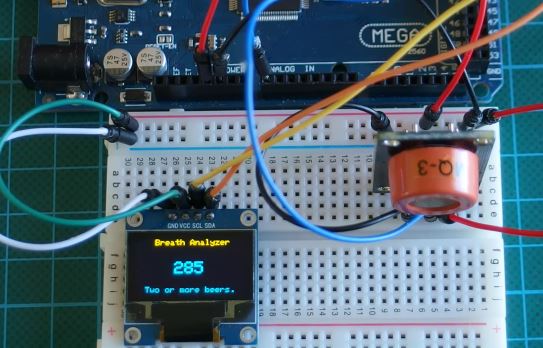
Copy the code, paste in the Arduino IDE and upload to your board. You should see something like the image below after its warm. The Arduino code is attached in a zip file at the end of the project.
That’s it for this tutorial. As usual, let me know if you have any questions or comments via the comment section.
You can watch the video of this tutorial here.


Hi, How Accurate is this Sensor, can it compete with the devices that the Police use?