Arduino distance meter with Ultrasonic Sensor (HC SR04) and Nokia 5110 LCD display
- Nick Koumaris
- http://educ8s.tv/
- info@educ8s.tv
- 8.677 Views
- moderate
- Tested
Introduction
Measuring distance is so important in today’s world that things like driverless cars will be impossible without it, that description is probably enough to describe how important knowing the distance between two objects can be. For that reason, today we will be building a distance meter using the Arduino and the HC-SR04 ultrasonic sensor.
The HC-SR04 ultrasonic sensor is a cheap ranging sensor capable of measuring a distance between 20 – 400cm without contact and at an accuracy of up to 3mm. The sensor is made up of a transmitter and receiver with operating frequency of around 40khz. It uses the echo principle for distance measurement by emitting an ultrasonic wave of 40khz. If there is an object in its path, the emitted wave is reflected and the reflected signal is received via the receiver. The time elapsed between the transmission of the signal and the reception of the echo is then used to determine the distance between the sensor and an object in its path.
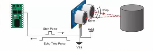
The sensor has four pins, VCC, GND, Trig and Echo with trig and echo representing the transmitter and receiver pins respectively.

Some other features of the sensor includes;
- Power Supply:+5V DC
- Quiescent Current : <2mA
- Working Current: 15mA
- Effectual Angle: <15°
- Ranging Distance : 2cm – 400 cm/1″ – 13ft
- Resolution : 0.3 cm
- Measuring Angle: 30 degree
- Trigger Input Pulse width: 10uS
- Dimension: 45mm x 20mm x 15mm
The goal of this tutorial will be to measure distance using the ultrasonic sensor and display it on both the serial monitor and the Nokia 5110 LCD.
Required Components
The following components are needed for this project;
As usual, the exact components used for this tutorial can be bought by following the link attached to each of them.
Schematics
Connect the components as shown in the schematics below.
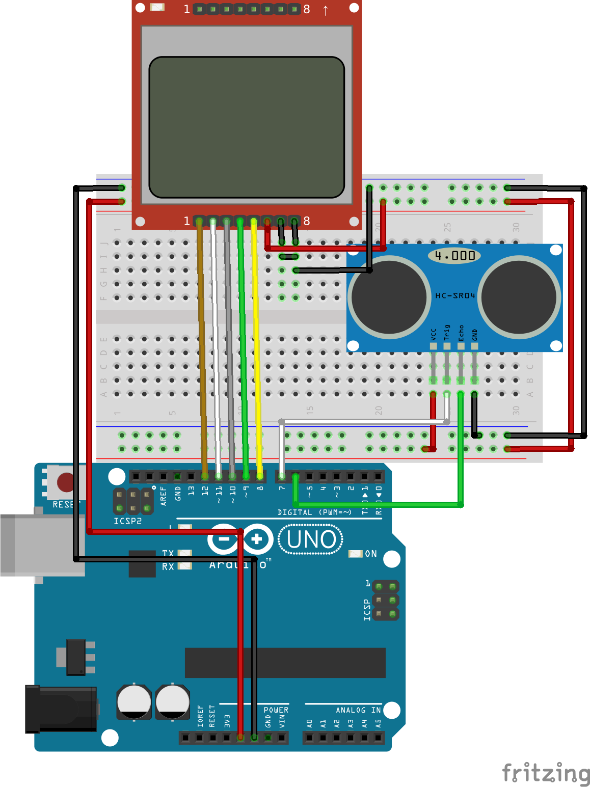
To make the schematics easy to follow, as usual, the pin maps showing how each component connects to the other is described below. Connecting the N0kia 5110 LCD to the Arduino is an art that we have perfected over several tutorials, an example of which can be found here, but for the purpose of this tutorial, we will still include the pin map so you can easily connect it if following that schematic is a little bit difficult. The Ultrasonic, on the other hand, is a very easy component to work with, it has just four pins and all at the same voltage/logic level at which the Arduino operates making it almost plug and play.
HC-SR04 to Arduino Pin Map
HC-SR04 - Arduino
Vcc - 5v
Trig - D7
Echo - D6
GND - GND
Nokia 5110 LCD to Arduino Pin Map
Pin 1(RST) – D12
Pin 2(CE) – D11
Pin 3(DC) – D1
Pin 4(DIN) – D9
Pin 5(CLK) – D8
Pin 6(VCC) - VCC
Pin 7(LIGHT) - GND
Pin 8(GND) - GND
Double check the connections one last time to be sure everything is as it should be.
Code
There are two codes for this project, the first one is for people who don’t have the Nokia5110 LCD display and are comfortable with viewing the data over serial monitor.The second one integrates the LCD display and allows the display of the value on the LCD.
The working of the code can be better understood by going through the description of how the HC-SR04 works above. The goal of the code is, simply put, to send a signal out via the trigger pin of the ultrasonic sensor and calculate the time it takes to receive the signal back via the echo pin of the sensor. Convert this time to distance and display either on the serial monitor (code sample 1) or on the Nokia 511o LCD(code sample 2). Both codes, as usual, are attached to the zip file under the download section.
Code for Distance Meter without Display
The first thing we will do is declare the pins of the Arduino to which the pins of the ultrasonic sensor are connected.
//Written by Nick Koumaris
//info@educ8s.tv
//educ8s.tv
#define echoPin 6 // Echo Pin
#define trigPin 7 // Trigger Pin
Next, we initialize variables that will be used to store some of the information that we will be working with.
int maximumRange = 250; // Maximum range needed
int minimumRange = 1; // Minimum range needed
long duration, distance; // Duration used to calculate distance
With that out of the way, we then move into the void setup() function. Since we will be primarily be using the serial monitor to display the distance, we must initialize it, with a baud rate of 9600, after which we set the pin mode of the sensor’s pin with the trigger pin being set as output and echo pin as input.
void setup() {
 Serial.begin (9600);
 pinMode(trigPin, OUTPUT);
 pinMode(echoPin, INPUT);
}
Next, we write the void loop() function.
To simplify things, a function was used to get the distance from the ultrasonic sensor and then display it within the void loop. The first thing we do is call the function to read the distance, then an if statement is used to check if the distance read by the sensor, is within the sensor’s range to reduce error which occurs when the sensor’s limit is exceeded.
If the sensor is within range, it is printed else, out of range is displayed.
void loop() {

readDistance();

if(distance>minimumRange && distance < maximumRange)
{
 Serial.println(distance);
}else
{
  Serial.println("Out of range...");
}
 delay(50);
}
The distance calculation is done using the readdistance() function. The function achieves the distance determination by sending a pulsed signal out through the trig pin by turning it low and high with a delay in between, and the echo is received via the echo pin using the Arduino inbuilt pulsein function. As specified by the datasheet, the time is then divided by 58.2 to get the distance in Cm.
int readDistance()
{
 digitalWrite(trigPin, LOW);
 delayMicroseconds(2);

 digitalWrite(trigPin, HIGH);
 delayMicroseconds(10);

 digitalWrite(trigPin, LOW);
 duration = pulseIn(echoPin, HIGH);

 distance = duration/58.2;
}
The full code is available below.
//Written by Nick Koumaris
 //info@educ8s.tv
//educ8s.tv

#define echoPin 6 // Echo Pin
#define trigPin 7 // Trigger Pin

int maximumRange = 250; // Maximum range needed
int minimumRange = 1; // Minimum range needed
long duration, distance; // Duration used to calculate distance

void setup() {
 Serial.begin (9600);
 pinMode(trigPin, OUTPUT);
 pinMode(echoPin, INPUT);
}

void loop() {

readDistance();

if(distance>minimumRange && distance < maximumRange)
{
 Serial.println(distance);
}else
{
  Serial.println("Out of range...");
}
 delay(50);
}

int readDistance()
{
 digitalWrite(trigPin, LOW);
 delayMicroseconds(2);

 digitalWrite(trigPin, HIGH);
 delayMicroseconds(10);

 digitalWrite(trigPin, LOW);
 duration = pulseIn(echoPin, HIGH);

 distance = duration/58.2;
}
Code for Distance Meter with Display
The second code as explained previously is for those who have the Nokia 5110 LCD.
To be able to use the Nokia 5110 LCD easily, we will be using its library which can be downloaded from this link. To give the display a good look we created a UI file which is part of the LCD code file attached to the zip file under the download section. How to work with the Nokia 5110 LCD to create your own UI, custom graphics etc has been covered in a previous tutorial here.
To get started with the code, we include the LCD library and define the pins to which both the ultrasonic sensor and LCD are connected to on the Arduino.
//Written by Nick Koumaris
//info@educ8s.tv
//educ8s.tv

#include <LCD5110_Graph.h>

#define echoPin 6 // Echo Pin
#define trigPin 7 // Trigger Pin

LCD5110 lcd(8,9,10,12,11);
Next, we declare the font that will be used for the LCD and the UI file.
extern unsigned char BigNumbers[];
extern uint8_t ui[];
Next, we set the minimum and maximum range of values which the ultrasonic sensor recognizes and we declare the variables, (distance and duration) which will be used to store corresponding data in the code.
int maximumRange = 250; // Maximum range needed
int minimumRange = 1; // Minimum range needed
long duration, distance; // Duration used to calculate distance
Next, we proceed to the setup() function where we set the pin modes of the Ultrasonic sensor pins, after which we initialize the LCD and instruct it to use the fonts we declared initially.
void setup() {
 pinMode(trigPin, OUTPUT);
 pinMode(echoPin, INPUT);
 lcd.InitLCD();
 lcd.setFont(BigNumbers);
}
With that done, we move into the void loop section.
We initialize the string length to zero, clear the screen and then draw the UI we created, after which we call the read distance function, calculate the string length of the distance received and display it on the LCD using the print distance function.
void loop() {
 int stringLength = 0;

 lcd.clrScr();
 lcd.drawBitmap(0, 0, ui, 84, 48);
 distanceString = readSensor();

 stringLength = distanceString.length();
 printDistance(stringLength);
 lcd.update();
 delay(50);
}
The full code is available below.
//Written by Nick Koumaris
//info@educ8s.tv
//educ8s.tv

#include <LCD5110_Graph.h>

#define echoPin 6 // Echo Pin
#define trigPin 7 // Trigger Pin

LCD5110 lcd(8,9,10,12,11);

extern unsigned char BigNumbers[];
extern uint8_t ui[];

int maximumRange = 250; // Maximum range needed
int minimumRange = 1; // Minimum range needed
long duration, distance; // Duration used to calculate distance


String distanceString = "0";

void setup() {
 pinMode(trigPin, OUTPUT);
 pinMode(echoPin, INPUT);
 lcd.InitLCD();
 lcd.setFont(BigNumbers);
}

void loop() {
 int stringLength = 0;

 lcd.clrScr();
 lcd.drawBitmap(0, 0, ui, 84, 48);
 distanceString = readSensor();

 stringLength = distanceString.length();
 printDistance(stringLength);
 lcd.update();
 delay(50);
}

void printDistance(int length)
{
  switch(length)
    {
    case 1:  lcd.print(distanceString,38,19); break;
    case 2:  lcd.print(distanceString,24,19); break;
    case 3:  lcd.print(distanceString,10,19); break;
    default:  lcd.print(distanceString,0,19); break;
  }
}

String readSensor()
{
  String distanceS = "0";
 digitalWrite(trigPin, LOW);
 delayMicroseconds(2);

 digitalWrite(trigPin, HIGH);
 delayMicroseconds(10);

 digitalWrite(trigPin, LOW);
 duration = pulseIn(echoPin, HIGH);

 distance = duration/58.2;
 distanceS = String(distance);
 if(distance>maximumRange || distance<minimumRange)
 {
   distanceS = "---";
 }

 delay(50);
 return distanceS;
}
Demo
Connect the Arduino board to your computer, launch the IDE and paste the code into it. Don’t forget to add the UI file to the Arduino sketch folder for the code before uploading as this may cause errors to occur. The UI file is part of the files in the zip file under the downloads section.
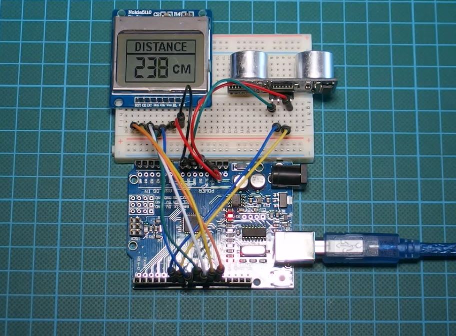
Upload the code to your board and you should see the distance on your display like the image above. If you are using the Serial monitor as the display, launch it too, you should see the distance streaming in as seen in the image below.
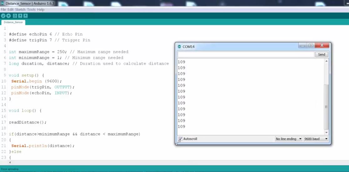
works right? Yea!
That’s it for this tutorial guys, as usual, you can drop comments and questions via the comment section.
Till next time
You can watch the video of this tutorial on youtube here.


