Battery (Lithium, NiMH, NiCd) Capacity Tester Using Arduino
- Emmanuel Odunlade
- https://twitter.com/emmaodunlade
- emmaodunlade@gmail.com
- 13.684 Views
- moderate
- Tested
The increased interest in IoT and electric automobiles around the world is driving an increase in the use of Lithium-Ion/Lithium-Polymer/NiCd/NiMH batteries as more devices and applications are using them, due to their high energy storage capacity to size ratio. This increased interest is, however, causing an increase in the number of batteries with “fake” ampere-hours ratings in the market. These fake ratings could lead to the failure of several projects, especially IoT projects in which developers factor in the Battery ratings in their On-time calculations. As such, to find a way of mitigating the failure-risks this problem poses, for today’s tutorial, we are going to build a battery capacity tester which can be used to get the correct energy storage capacity of any Lithium-Ion/Lithium-Polymer/NiCd/NiMH batteries (with voltage below <5v).
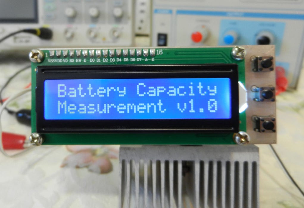
There are quite a number of battery testing projects on the internet, each with a different approach, but for today’s tutorial we will be chronicling the efforts of Instructables user: Sam Moshiri, due to the quality of his build and its standalone and compact nature. The goal of the project according to him was to build a compact, easy-to-build device, capable of measuring the capacity of almost any kind of battery (< 5V) using an adjustable constant load setup with an LCD on which the capacity of the battery is displayed.
The idea behind the constant load current setup is simple. If you draw a constant current from a battery over a particular period of time, you will be able to calculate the true ampere-hour capacity of the battery based on the amount of voltage that was dropped during that time. To achieve the constant load current, a resistor network with an LM358 operation amplifier and a MOSFET was used. The setup has two push buttons (+ and -) that allow users to set the load current before the process starts, and a third push-button to reset the board when it’s time to test another battery. The Battery’s voltage is fed into one of the analog pins on an Arduino Nano which monitors the voltage drop based on the preset current draw, calculates the battery capacity, and displays it on a 16×2 LCD Display.
At the end of this tutorial, you would know not only how to determine the battery capacity, but also how to design for constant load / constant current draw and use a 16×2 LCD display with the Arduino.
Ready? Let’s dive in!
Required Components
The components required for this project are provided below:
- Arduino Nano
- 16 x 2 LCD Display
- LM358N
- Resistors – 4.7k(2), 47R(2), 1M, 10k, 3R
- Capacitors 100nF(6), 100uf-16V, 1000uF-16V
- Tact Switch (3)
- IRF3710
- Jumper Wires
- Battery Holder
- Variable Power Supply
Although the project was implemented on a PCB to make it compact, all of the components used are of DIP type to make it easy to solder for everyone, irrespective of the level of their soldering skills. The Arduino Nano was used because it can be easily soldered on a PCB, asides this reason, any other board could have been used.
Schematics
As earlier mentioned, the project was implemented using a PCB to make it portable. The PCB was designed using Altium and all the files are attached under the download section of the tutorial. The components are connected as shown in the schematics below;

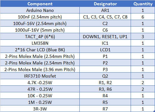
A comprehensive BOM showing how each component fits into the schematics above is shown in the table below:
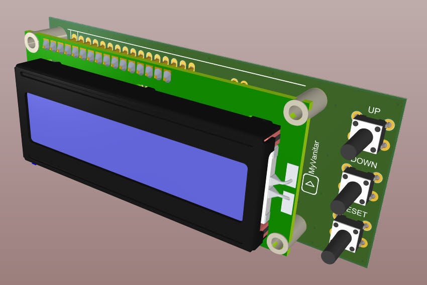
To create the PCB, Sam used the SamacSys component libraries, because of features like the industrial IPC standards which they follow and the fact that they are free. The Libraries were installed using the Altium Library plugin. The PCB after development is shown in the image below along with the assembled version of the board.
Code
The code for this project is quite straightforward. We will basically monitor the time it takes for a battery to get to a predefined “low” value, and calculate the battery’s capacity using the depletion rate and the preset constant load current that was drawn from it. The whole process is displayed on an LCD in an interactive manner.
To reduce the amount of code to be written, we will use the Arduino Liquid Crystal library along with the JCbutton library. The liquid crystal library which comes preinstalled on the Arduino will be used to interact with the 16×2 LCD, while the JCbutton library, which can be downloaded from the attached link, is used in processing the state of the tact buttons, determining when it has been pressed, long pressed, etc., while also handling things like debounce.
As usual, I will do a quick explanation of how the code works with a focus on sections that I feel might be difficult to follow.
The code starts by importing the two libraries that will be used.
#include <LiquidCrystal.h>
#include <JC_Button.h>
Next, we create a variable to hold the minimum level to which the battery is allowed to drop, and several other variables to store different values. The Current array is a series of value which is matched to the rotation of the R7 potentiometer which determines the load current.
const float Low_BAT_level = 3.2;
//Current steps with a 3R load (R7)
const int Current[] = {0, 37, 70, 103, 136, 169, 202, 235, 268, 301, 334, 367, 400, 440, 470, 500, 540};

const byte RS = 2, EN = 3, D4 = 4, D5 = 5, D6 = 6, D7 = 7;
const byte PWM_Pin = 10;
const byte Speaker = 12;
const int BAT_Pin = A0;
int PWM_Value = 0;
unsigned long Capacity = 0;
int ADC_Value = 0;
float BAT_Voltage = 0;
byte Hour = 0, Minute = 0, Second = 0;
bool calc = false, Done = false;
Next, we create an instance of the Liquid Crystal library with the EN, RS and other pins of the Arduino to which the LCD is connected, as arguments.
LiquidCrystal lcd(RS, EN, D4, D5, D6, D7);
We also create instances of the button library for the two major buttons (up and down).
Button UP_Button(16, 25, false, true);
Button Down_Button(15, 25, false, true);
With this done, we move to the void setup() function. We start the function by setting the pinMode of the buzzer and PWM pin as output.
void setup() {

  pinMode(PWM_Pin, OUTPUT);
  pinMode(Speaker, OUTPUT);
After this, we initialize the two buttons we created along with the LCD.
UP_Button.begin();
Down_Button.begin();
lcd.setCursor(0, 0);
lcd.begin(16, 2);
After initializing the LCD, display a splash screen of some sort with the name of the project and the version. After 3s, the display is cleared and it displays the Load Adj: up/Down button showing it is waiting for the user to set a load current.
  lcd.print("Battery Capacity");
  lcd.setCursor(0, 1);
  lcd.print("Measurement v1.0");
  delay(3000);
  lcd.clear();
  lcd.print("Load Adj:UP/Down");
  lcd.setCursor(0, 1);
  lcd.print("0");

}
Next is the void loop() function. We start the function by reading the tact buttons.
void loop() {
  UP_Button.read();
  Down_Button.read();
Each time the Up button is pressed, it adds 5 to the Pwm_Value variable which is used as the load current indicator. The inverse is true for the Down button. For each of the button pressed, the user is provided with visual feedback of the increase or decrease in the PWM_value, on the Display.
if (UP_Button.wasReleased() && PWM_Value < 80 && calc == false)
 {
   PWM_Value = PWM_Value + 5;
   analogWrite(PWM_Pin, PWM_Value);
   lcd.setCursor(0, 1);
   lcd.print("     ");
   lcd.setCursor(0, 1);
   lcd.print(String(Current[PWM_Value / 5]) + "mA");
 }

 if (Down_Button.wasReleased() && PWM_Value > 1 && calc == false)
 {
   PWM_Value = PWM_Value - 5;
   analogWrite(PWM_Pin, PWM_Value);
   lcd.setCursor(0, 1);
   lcd.print("     ");
   lcd.setCursor(0, 1);
   lcd.print(String(Current[PWM_Value / 5]) + "mA");
 }
If the Up button is long pressed (indicated by 1000ms), the system switches mode as it assumes the user has selected a load current that satisfies them. The mode switch involves invoking the timer interrupt() function which handles all the calculations involved with determining the capacity of the battery. This cycle is repeated as the loop continues.
if (UP_Button.pressedFor(1000) && calc == false)
{
  digitalWrite(Speaker, HIGH);
  delay(100);
  digitalWrite(Speaker, LOW);
  lcd.clear();
  timerInterrupt();
}
The timerInterrupt() function handles most of the project’s heavy lifting. It continuously monitors the battery voltage and as long as it’s not yet at the preset Low_BAT_Level, it increments the time. As soon as the measured battery voltage becomes less than the Low_BAT_Level, it stops the time increment and uses it to estimate the capacity of the battery. At this point, the buzzer is turned on and off in a pattern to indicate the completion of the process.
void timerInterrupt() {
  calc = true;
  while (Done == false) {
    Second ++;
    if (Second == 60) {
      Second = 0;
      Minute ++;
      lcd.clear();
    }
    if (Minute == 60) {
      Minute = 0;
      Hour ++;
    }
    lcd.setCursor(0, 0);
    lcd.print(String(Hour) + ":" + String(Minute) + ":" + String(Second));
    lcd.setCursor(9, 0);
    ADC_Value = analogRead(BAT_Pin);
    BAT_Voltage = ADC_Value * (5.0 / 1024);
    lcd.print("V:" + String(BAT_Voltage));
    lcd.setCursor(0, 1);
    lcd.print("BAT-C: Wait!...");

    if (BAT_Voltage < Low_BAT_level)
    {
      lcd.setCursor(0, 1);
      lcd.print("                ");
      lcd.setCursor(0, 1);
      Capacity =  (Hour * 3600) + (Minute * 60) + Second;
      Capacity = (Capacity * Current[PWM_Value / 5]) / 3600;
      lcd.print("BAT-C:" + String(Capacity) + "mAh");
      Done = true;
      PWM_Value = 0;
      analogWrite(PWM_Pin, PWM_Value);
      digitalWrite(Speaker, HIGH);
      delay(100);
      digitalWrite(Speaker, LOW);
      delay(100);
      digitalWrite(Speaker, HIGH);
      delay(100);
      digitalWrite(Speaker, LOW);
    }

    delay(1000);
  }
}
The complete code for the project is available below and also attached under the download section.
#include <LiquidCrystal.h>
#include <JC_Button.h>

const float Low_BAT_level = 3.2;

//Current steps with a 3R load (R7)
const int Current[] = {0, 37, 70, 103, 136, 169, 202, 235, 268, 301, 334, 367, 400, 440, 470, 500, 540};

const byte RS = 2, EN = 3, D4 = 4, D5 = 5, D6 = 6, D7 = 7;
const byte PWM_Pin = 10;
const byte Speaker = 12;
const int BAT_Pin = A0;
int PWM_Value = 0;
unsigned long Capacity = 0;
int ADC_Value = 0;
float BAT_Voltage = 0;
byte Hour = 0, Minute = 0, Second = 0;
bool calc = false, Done = false;

LiquidCrystal lcd(RS, EN, D4, D5, D6, D7);

Button UP_Button(16, 25, false, true);
Button Down_Button(15, 25, false, true);

void setup() {

  pinMode(PWM_Pin, OUTPUT);
  pinMode(Speaker, OUTPUT);

  analogWrite(PWM_Pin, PWM_Value);

  UP_Button.begin();
  Down_Button.begin();

  lcd.setCursor(0, 0);
  lcd.begin(16, 2);
  lcd.print("Battery Capacity");
  lcd.setCursor(0, 1);
  lcd.print("Measurement v1.0");
  delay(3000);
  lcd.clear();
  lcd.print("Load Adj:UP/Down");
  lcd.setCursor(0, 1);
  lcd.print("0");

}

void loop() {
  UP_Button.read();
  Down_Button.read();

  if (UP_Button.wasReleased() && PWM_Value < 80 && calc == false)
  {
    PWM_Value = PWM_Value + 5;
    analogWrite(PWM_Pin, PWM_Value);
    lcd.setCursor(0, 1);
    lcd.print("     ");
    lcd.setCursor(0, 1);
    lcd.print(String(Current[PWM_Value / 5]) + "mA");
  }

  if (Down_Button.wasReleased() && PWM_Value > 1 && calc == false)
  {
    PWM_Value = PWM_Value - 5;
    analogWrite(PWM_Pin, PWM_Value);
    lcd.setCursor(0, 1);
    lcd.print("     ");
    lcd.setCursor(0, 1);
    lcd.print(String(Current[PWM_Value / 5]) + "mA");
  }
  if (UP_Button.pressedFor(1000) && calc == false)
  {
    digitalWrite(Speaker, HIGH);
    delay(100);
    digitalWrite(Speaker, LOW);
    lcd.clear();
    timerInterrupt();
  }

}

void timerInterrupt() {
  calc = true;
  while (Done == false) {
    Second ++;
    if (Second == 60) {
      Second = 0;
      Minute ++;
      lcd.clear();
    }
    if (Minute == 60) {
      Minute = 0;
      Hour ++;
    }
    lcd.setCursor(0, 0);
    lcd.print(String(Hour) + ":" + String(Minute) + ":" + String(Second));
    lcd.setCursor(9, 0);
    ADC_Value = analogRead(BAT_Pin);
    BAT_Voltage = ADC_Value * (5.0 / 1024);
    lcd.print("V:" + String(BAT_Voltage));
    lcd.setCursor(0, 1);
    lcd.print("BAT-C: Wait!...");

    if (BAT_Voltage < Low_BAT_level)
    {
      lcd.setCursor(0, 1);
      lcd.print("                ");
      lcd.setCursor(0, 1);
      Capacity =  (Hour * 3600) + (Minute * 60) + Second;
      Capacity = (Capacity * Current[PWM_Value / 5]) / 3600;
      lcd.print("BAT-C:" + String(Capacity) + "mAh");
      Done = true;
      PWM_Value = 0;
      analogWrite(PWM_Pin, PWM_Value);
      digitalWrite(Speaker, HIGH);
      delay(100);
      digitalWrite(Speaker, LOW);
      delay(100);
      digitalWrite(Speaker, HIGH);
      delay(100);
      digitalWrite(Speaker, LOW);
    }

    delay(1000);
  }
}
Demo
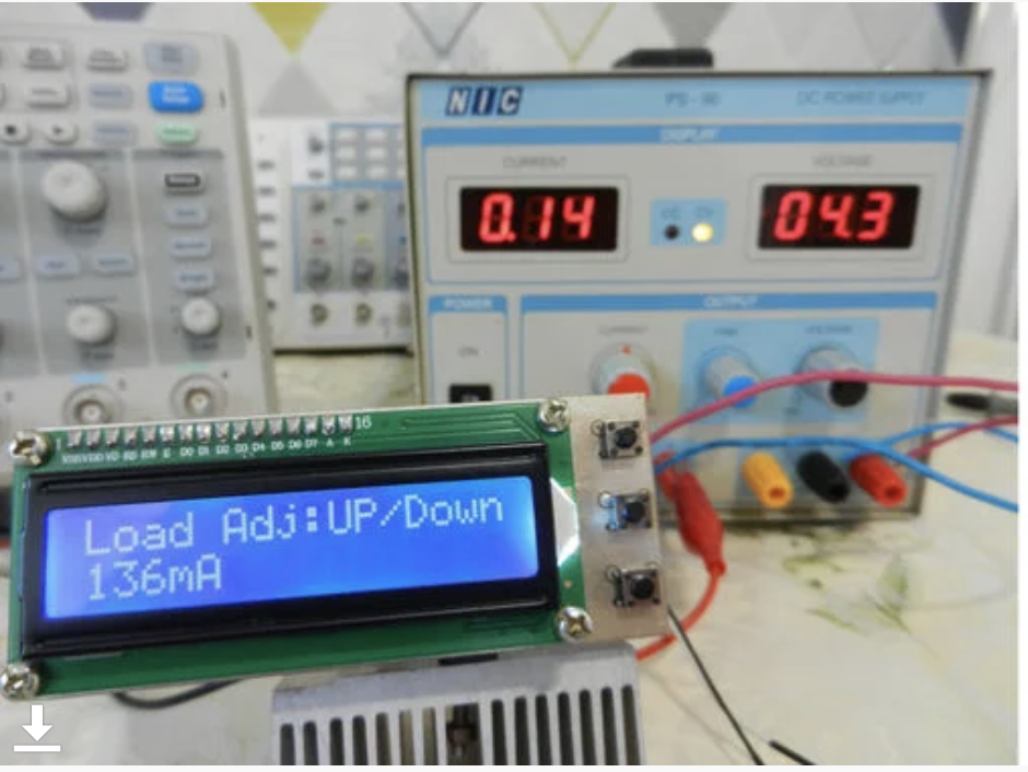
With the code completed and your PCB ready, connect the Arduino Nano to your computer and upload the code to it. After the code upload, you should see the LCD come up with the splash screen as shown in the image below.

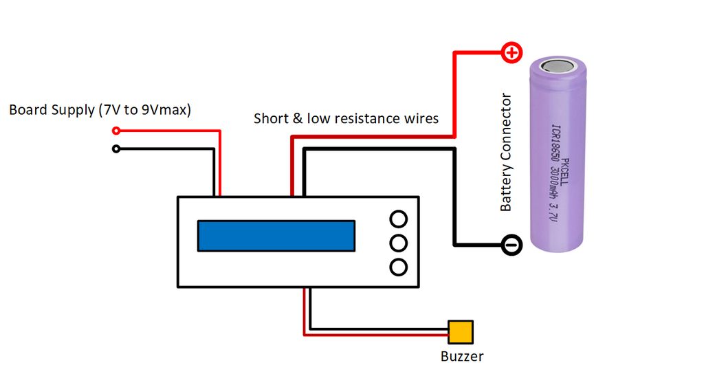
With the code uploaded, we then need to power the board via an external power supply and connect a battery to it as shown in the image below. Based on this current design, you should only power the board with a maximum of 9V.
With the power supply and battery connected, set your desired load Current using the up and down buttons then press and hold the up button till you hear the buzzer beeps, to kick start the process.
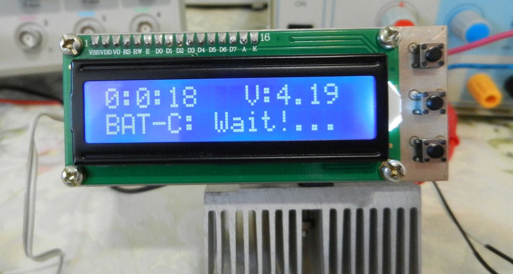
As the process proceeds, an update will be provided on the screen, showing the time that has elapsed and the voltage of the battery.
At the end of the process, the battery’s true capacity is displayed as shown in the image below.
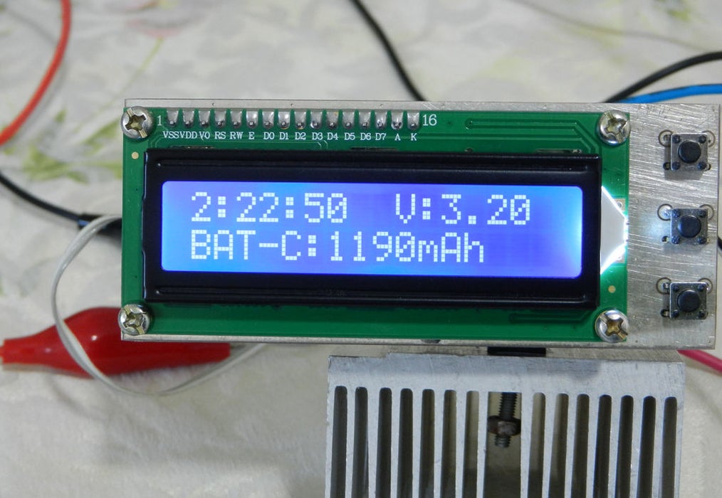
That’s it. For the demo, a battery rated 8800mAh was used but at the end of the test, the battery was discovered to only have an energy capacity of 1190mAh.
That’s it for this tutorial guy’s thanks for reading. As usual, you can reach out to me via the comment section if you have any questions or difficulties replicating the project.
References:


Hello, I want to point out that there is no download section fir the project code or other assets as you mentioned.
We will add it soon. Sorry for the inconvenience.
Hi can you build this product for me, please let me know if itis possible.
Please contact Sam for this task: https://www.instructables.com/member/sam_moshiri/
Was the Arduino code for this project ever posted in the Downloads section? I can’t find it anywhere.
hi,How are the current values used in the current array obtained?