Getting Started with the NodeMCU (ESP8266 Based Development Board)
- Emmanuel Odunlade
- https://twitter.com/emmaodunlade
- emmaodunlade@gmail.com
- 14.101 Views
- easy
- Tested
As the popularity of Arduino boards increased, the demand for boards which comes embedded with some of the add-ons used with the Arduino increased. One of the most popular add-ons were the WiFi modules which are used to connect Arduino boards to the internet. Several boards were released by different manufacturers which used the Arduino form factor and had onboard WiFi module, but none of these boards became as popular as the NodeMCU. Today, we will be exploring how to use the NodeMCU board in projects and especially how to easily program the board using the Arduino IDE.
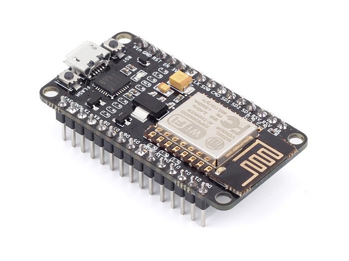
The NodeMCU is an ESP8266 WiFi based microcontroller board that helped overcome some of the difficulties associated with several versions of boards based on the ESP8266 WiFi module/chips from Espressif.
The Arduino came at a time when the IoT revolution was starting out and it gave makers the opportunity to be part of that revolution by building simple connected devices, combining the Arduino and several different kinds of WiFi and Ethernet modules/shields. All those modules were either too expensive or quite complex to use. So when the first version of the ESP8266 module (ESP-01) came to market, it was an absolute delight as the low price and quality drove the popularity of the chip. Users, however, quickly discovered several constraints from the power requirements to the breadboard unfriendliness of the chip. The chips had little (written in Chinese) or no documentation and this made them even more difficult to use. Several other versions of the modules were made but they all had similar constraints.
To resolve some of the issues associated with these modules, several breakout and development boards based on these modules were made such as the Wemos D1 (which worked like the Arduino Uno) and Wemos Mini boards, but none of them quite achieved the same level of popularity as the NodeMCU.
The NodeMCU board is essentially a breakout/development board for the ESP12E module by AI-thinker.
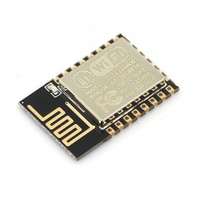
The ESP-12E itself, just like the previous modules, was difficult to work with, due to factors including: breadboard unfriendliness, it requires header pins that were not common on the market, and the only solution to these problems, that was envisioned at the time, was an adapter coupled with an FTDI breakout board and some other connections to make it breadboard friendly and easy to program.
The NodeMCU was the product of that search, incorporating all the required components on a single breadboard friendly, ready to use board while retaining the low cost with which the ESP-based boards were associated.
Some of the features of the board include;
- Arduino-like (software defined) GPIO
- Can be programmed using the Esplorer IDE or the Arduino IDE.
- Onboard USB-TTL converter for easy programming
- 10 onboard digital I/O pins, an analog pin along with pins for SPI, IIC, and 1-Wire communication protocols.
- Extensive WiFi capabilities (Can create an access point and/or join an existing one). It is used to connect devices to the internet to fetch/ upload data and can serve as a mini webserver for simple pages.
- Onboard PCB antenna.
- 3.3V logic level
Originally when the ESP8266 modules were released, to work in standalone mode, they had to be programmed using the ESplorer IDE which required a knowledge of the LUA programming language, but as things progressed, the board type was created for the Arduino IDE and someone can now easily program several ESP based boards, using the Arduino IDE. This tutorial serves to show how easy someone can program the NodeMCU board using the Arduino IDE.
Required Components
The following components are required to follow this project:
- NodeMCU Development Board
- USB Cable
- Breadboard
- Jumper Wires
- 220/100 ohms resistor
- LED
The project also requires using the latest Arduino IDE which can be downloaded from Arduino’s official website..
Schematics
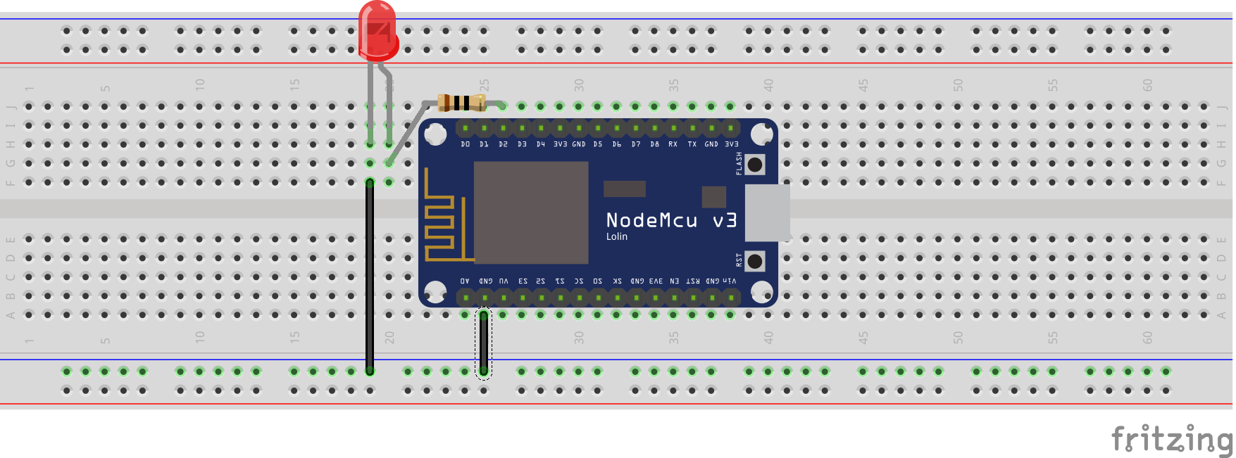
For this project, we will do the hello world of embedded programming, which is blinking an LED to demonstrate the use of the nodeMCU, so our schematics involves the connection of an LED to the nodeMCU as shown below.
Preparing the Arduino IDE
Before writing the code for the project, it is important to install all the packages necessary to make the board compatible with the Arduino IDE. We will essentially install two things:
- The NodeMCU Arduino Core
- The ESP8266 library for Arduino.
1. The NodeMCU Arduino Core
To make it easier to integrate other open source boards with the Arduino IDE, the Arduino team included a board manager in recent IDEs. Through the board manager, new boards (essentially software-based components required for the Arduino IDE to be able to upload code to a particular MCU) can be added to the IDE. These software-based components called cores are usually developed by manufacturers of the board (like Sparkfun does for its boards) or a group of users with the desire to see their board to work with the Arduino IDE.
The ESP8266 core for the Arduino IDE, which is compatible with the node MCU, was developed by members of the community who were interested in pushing the use of the board and can be found on the ESP8266 Github page.
Follow the steps below to install the board core on the Arduino IDE.
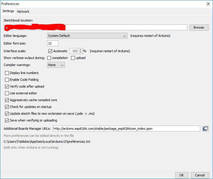
- Open the preferences window from the Arduino IDE. Go to File > Preferences
- On the preferences window, locate the “Additional Board Manager URLs” text box and enter http://arduino.esp8266.com/stable/package_esp8266com_index.json into the field as shown below and click the OK button.
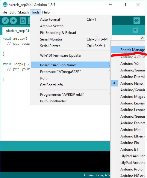
- Next, open the Arduino board manager. Go to tools>Boards>Boards manager
- When the board manager opens up, enter ESP into the search bar and scroll to the bottom, you will see ESP8266 created by the ESP8266 community, click on install as shown below.
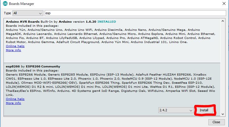
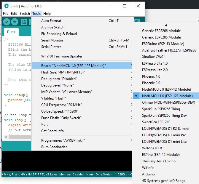
Installing the ESP8266 core will automatically install the ESP8266 library which will make easier writing code for the NodeMCU. After board installation, select the board going to tools>board>NodeMCU 1.0
By selecting this board, all the examples associated with the NodeMCU board will be loaded up. The code for today’s tutorial will be based on one of those examples.
Code
For today’s tutorial, we will blink a LED connected to pin D2 of the NodeMCU using the blink example that came with the core installation we did earlier.
Load the example by going to file>examples>examples for nodemcu>esp8266>blink

The blink example is probably the most common of all the examples associated with the Arduino but for the sake of those, I will explain it a bit.
We start the code by declaring the pin of the NodeMCU to which our LED is connected.
int LEDpin = 2;
Next is the void setup() function. All we need to do under this is to set the pin to which our led is connected as an output.
void setup() {
  pinMode(LEDpin, OUTPUT);     // Initialize pin D2 as an output
}
Lastly, the void loop function. Here we create lines of code to turn the LED on and off after certain intervals to create the blink effect.
void loop() {
  digitalWrite(LEDpin, LOW);   // Turn the LED on (Note that LOW is the voltage level
  // but actually the LED is on; this is because
  // it is active low on the ESP-01)
  delay(1000);                      // Wait for a second
  digitalWrite(LEDpin, HIGH);  // Turn the LED off by making the voltage HIGH
  delay(2000);                      // Wait for two seconds (to demonstrate the active low LED)
}
The complete code is written below.
int LEDpin = 2;

void setup() {
  pinMode(LEDpin, OUTPUT);     // Initialize the LEDpin as an output
}

// the loop function runs over and over again forever
void loop() {
  digitalWrite(LEDpin, LOW);   // Turn the LED on (Note that LOW is the voltage level
  // but actually the LED is on; this is because
  // it is active low on the ESP-01)
  delay(1000);                      // Wait for a second
  digitalWrite(LEDpin, HIGH);  // Turn the LED off by making the voltage HIGH
  delay(2000);                      // Wait for two seconds (to demonstrate the active low LED)
}
Demo
Upload the code to the NodeMCU. After a while, you should see the connected LED start blinking.
The NodeMCU is certainly capable of a whole lot more than has been demonstrated in today’s tutorial but I hope we have been able to get you started and on the next few tutorials we will be able to dive deeper into the use of the board.


