Network Clock using ESP8266 and OLED display
- Emmanuel Odunlade
- https://twitter.com/emmaodunlade
- emmaodunlade@gmail.com
- 17.791 Views
- Tested
There are several situations where using an RTC could adversely affect your project by increasing cost, size, time accuracy or IO requirements. To prevent this, especially in ESP/WiFi-based or other clock-reliant projects, makers usually turn to obtain time information from NTP servers. I recently came across a project by BitsandBlobs which used standalone NTP Servers and I felt it might be one of the best ways to introduce to this concept. So for today’s tutorial, we will build an NTP Based Network Time Clock based on “BitsandBlobs” build.
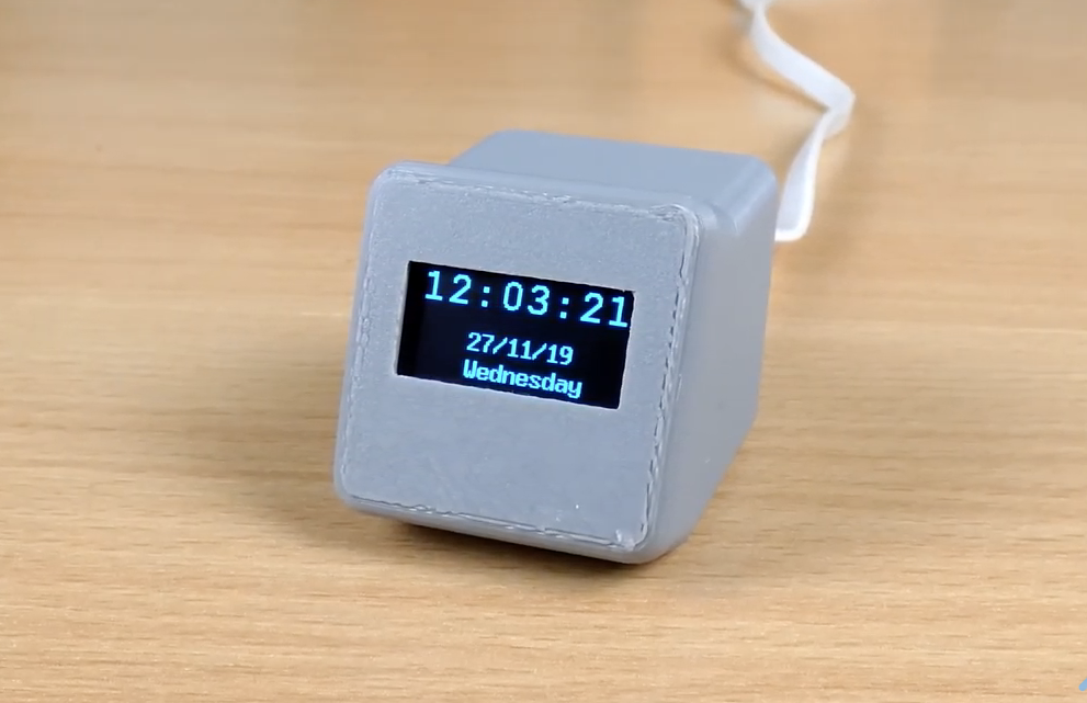
NTP (Network Time Protocol) is an internet protocol used for synchronizing clocks on computer networks within a few milliseconds of universal coordinated time (UTC). Using this protocol, devices can request and receive UTC data from an NTP server which usually receives precise time from an atomic clock.
The WiFi capabilities of the ESP8266 based Wemos D1 mini will be used in obtaining time information from a public NTP server and it will be displayed in a user-friendly manner on an OLED display.
At the end of this project, you would know not only how to obtain time information from NTP servers, but also how to use the WemosD1 for your WiFi projects.
Required Components
The following components are required to build this project:
- Wemos D1 Mini
- 0.96″ I2C OLED Display
- Jumper Wires
- BreadBoard (Optional)
The components can be purchased from the attached links. While an interesting enclosure was built for this project, for those who don’t have access to a 3D printer and don’t want to solder the components, you can go for the option of implementing the project on a breadboard.
Schematics
Thanks to the use of just two components, the schematics for today’s project is super straightforward. The OLED display being used communicates with the host microcontroller via I2C as such all we need do is connect the display to the I2C pins of the Wemos D1 mini as shown in the schematics below:
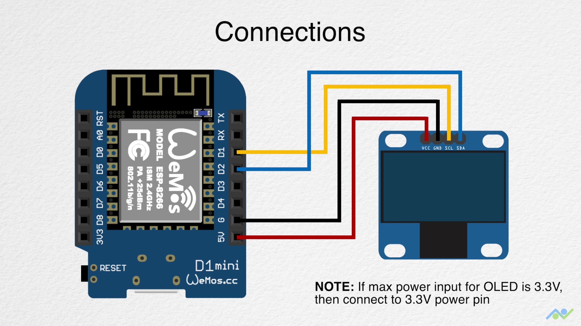
To make the connections easier to follow, a pin-pin map is provided below:
Wemos D1 – OLED
D1 - SCL
D2 - SDA
5v - VCC
GND - GND
It is important to note the maximum input voltage of your OLED display and be sure it is 5V tolerant. You should connect the VCC pin of the OLED to the Wemos D1’s 3.3v pin if 5V is too high for the display.
With the schematics complete, we can now proceed to the code for the project.
Code
The Arduino IDE is used for the code developing of this project, as such, if this is the first time are using an ESP8266 based board with the IDE, you will need to install the ESP8266 support for it. Follow this tutorial we wrote a while back on “Programming an ESP8266 Board with the Arduino IDE” to get it done.
The algorithm behind the code for today’s project is quite straightforward. We start by connecting the Wemos D1 to the internet via a WiFi Access point and access an NTP server to obtain the network time. We convert network time to our local time equivalent and display the local time on the OLED display.
To make writing the code easier, we will use some libraries including; the ESP8266WIFI library, the Time library, and the U8g2 library. The ESP8266WIFI library is used for everything related to connecting the Wemos to the internet through a WiFi access point, while the Time Library has function implementations that enable us easily extract time from NTP servers, and the U8g2 library allows us to interact with the OLED and display text on it in fancy fonts. The ESP8266WiFi and Time library comes pre-installed with the ESP8266 Arduino IDE support while the U8g2 library will need to be installed via the Arduino Library Manager or by downloading from the link attached above.
With the libraries installed, we are now ready to go over the code. As usual, I will do a quick run through it and try to explain some of the concepts in it that might be difficult to follow.
We start as usual by including all the libraries that we will use.
#include <ESP8266WiFi.h>
#include <time.h>
#include <U8x8lib.h>
Next, we provide the credentials (SSID and Password) of the WiFi access point through which the Wemos will access the internet and also specify the address of the NTP server we will connect to along with the timezone string which is used to correct the clock from the NTP server and to match that of our timezone. Since time zones are different, and the clock will not be correct if you don’t augment it with the time zone string, you might need to visit Remote Monitoring System’s website to get the correct time zone string (TZ_INFO) for your particular location.
const char* ssid = "Access point's SSID";
const char* password = "Access point's PASSWORD";

const char* NTP_SERVER = "ch.pool.ntp.org";
const char* TZ_INFO    = "GMT+0BST-1,M3.5.0/01:00:00,M10.5.0/02:00:00";  // enter your time zone (https://remotemonitoringsystems.ca/time-zone-abbreviations.php)
Next, we declare a few important variables that will be used to store data during the program run and create an instance of the U8g2 library with the pins of the Wemos D1 to which the OLED is connected, as arguments.
tm timeinfo;
time_t now;
long unsigned lastNTPtime;
unsigned long lastEntryTime;

U8X8_SSD1306_128X64_NONAME_SW_I2C u8x8(/* clock=*/ SCL, /* data=*/ SDA, /* reset=*/ U8X8_PIN_NONE);   // OLEDs without Reset of the Display
Next is the void setup() function. We start the function by initializing the OLED display and Serial communication with a baud rate of 115200.
void setup()
{
  u8x8.begin();

  Serial.begin(115200);
  Serial.println("\n\nNTP Time Test\n");
Next, we connect the Wemos to the WiFI access point using the WiFi.begin() function with the credentials of the access point as arguments. The program is stalled in a perpetual loop till the Wemos has connected successfully to the access point.
WiFi.begin(ssid, password);

  Serial.print("Connecting to network");
  int counter = 0;
  while (WiFi.status() != WL_CONNECTED)
  {
    delay(200);
    if (++counter > 100)
      ESP.restart();
    Serial.print( "." );
  }
  Serial.println("\nWiFi connected\n\n");
Next, we use the configtime() function to initialize a connection with the NTP server and use the setenv() function to set the time zone. Timezone codes for different regions can be also be obtained from Nayarsystems github page.
configTime(0, 0, NTP_SERVER);
 // See https://github.com/nayarsystems/posix_tz_db/blob/master/zones.csv for Timezone codes for your region
 setenv("TZ", TZ_INFO, 1);
With that done, we then make attempts to sync the NodeMCU with the NTP server using the getNTPtime() function. If the sync is not successful, the ESP is restarted, but if successful, the current time from the NTP server is saved as the NTP time and millis() is kickstarted so the time can be tracked and updated locally.
if (getNTPtime(10))
  {
    // wait up to 10sec to sync
  }
  else
  {
    Serial.println("Time not set");
    ESP.restart();
  }
  showTime(&timeinfo);
  lastNTPtime = time(&now);
  lastEntryTime = millis();
}
Next, we move to the void loop() function.
The loop() function is quite straight forward. We simply get the time from the time using the getNTPtime() function and display it on the OLED with the showTime(&timeinfo) function. A delay of 1000ms is added to the code to ensure the text is displayed smoothly.
void loop()
{
  getNTPtime(10);
  showTime(&timeinfo);
  delay(1000);
}
The two key functions driving behind the code for the project are the getNTPtime() and the showTime() functions.
The getNTPtime uses the millis() function to keep track of the last time received from the NTP server and update the current time based on it. The time and date information are obtained from the data received from the NTP server and the “timeinfo” variable is updated with that data.
bool getNTPtime(int sec)
{
  {
    uint32_t start = millis();
    do
    {
      time(&now);
      localtime_r(&now, &timeinfo);
      delay(10);
    } while (((millis() - start) <= (1000 * sec)) && (timeinfo.tm_year < (2016 - 1900)));

    if (timeinfo.tm_year <= (2016 - 1900))
        return false;  // the NTP call was not successful

    Serial.print("Time Now: ");
    Serial.println(now);
  }
  return true;
}
The showtime() function, on the other hand, splits up the timeinfo variable and displays the time information including the date, day of the week, and clock, on the OLED display, as well as the serial monitor.
void showTime(tm *localTime)
{
  //print to serial terminal
  Serial.print(localTime->tm_mday);
  Serial.print('/');
  Serial.print(localTime->tm_mon + 1);
  Serial.print('/');
  Serial.print(localTime->tm_year - 100);
  Serial.print('-');
  Serial.print(localTime->tm_hour);
  Serial.print(':');
  Serial.print(localTime->tm_min);
  Serial.print(':');
  Serial.print(localTime->tm_sec);
  Serial.print(" Day of Week ");
  Serial.println(localTime->tm_wday);
  Serial.println();

  //display on OLED
  char time_output[30];

  u8x8.setFont(u8x8_font_courB18_2x3_f);
  u8x8.setCursor(0,0);
  sprintf(time_output, "%02d:%02d:%02d", localTime->tm_hour, localTime->tm_min, localTime->tm_sec);
  u8x8.print(time_output);

  u8x8.setFont(u8x8_font_8x13B_1x2_f);
  u8x8.setCursor(4,4);
  sprintf(time_output, "%02d/%02d/%02d", localTime->tm_mday, localTime->tm_mon + 1, localTime->tm_year - 100);
  u8x8.print(time_output);

  u8x8.setCursor(4,6);
  u8x8.print(getDOW(localTime->tm_wday));
}
The last function in the sketch is the getDOW() function which is used to convert the numeric day of the week value from the time struct, into a String(the name value).
char * getDOW(uint8_t tm_wday)
{
  switch(tm_wday)
  {
    case 1:
      return "Monday";
      break;

    case 2:
      return "Tuesday";
      break;

    case 3:
      return "Wednesday";
      break;

    case 4:
      return "Thursday";
      break;

    case 5:
      return "Friday";
      break;

    case 6:
      return "Saturday";
      break;

    case 7:
      return "Sunday";
      break;

    default:
      return "Error";
      break;
  }
}
The complete code for the project is provided below and also attached in the zip file under the download section.
#include <ESP8266WiFi.h>
#include <time.h>
#include <U8x8lib.h>

const char* ssid = "Access point's SSID";
const char* password = "Access point's PASSWORD";

const char* NTP_SERVER = "ch.pool.ntp.org";
const char* TZ_INFO    = "GMT+0BST-1,M3.5.0/01:00:00,M10.5.0/02:00:00";  // enter your time zone (https://remotemonitoringsystems.ca/time-zone-abbreviations.php)

tm timeinfo;
time_t now;
long unsigned lastNTPtime;
unsigned long lastEntryTime;

U8X8_SSD1306_128X64_NONAME_SW_I2C u8x8(/* clock=*/ SCL, /* data=*/ SDA, /* reset=*/ U8X8_PIN_NONE);   // OLEDs without Reset of the Display

void setup()
{
  u8x8.begin();

  Serial.begin(115200);
  Serial.println("\n\nNTP Time Test\n");
  WiFi.begin(ssid, password);

  Serial.print("Connecting to network");
  int counter = 0;
  while (WiFi.status() != WL_CONNECTED)
  {
    delay(200);
    if (++counter > 100)
      ESP.restart();
    Serial.print( "." );
  }
  Serial.println("\nWiFi connected\n\n");

  configTime(0, 0, NTP_SERVER);
  // See https://github.com/nayarsystems/posix_tz_db/blob/master/zones.csv for Timezone codes for your region
  setenv("TZ", TZ_INFO, 1);

  if (getNTPtime(10))
  {
    // wait up to 10sec to sync
  }
  else
  {
    Serial.println("Time not set");
    ESP.restart();
  }
  showTime(&timeinfo);
  lastNTPtime = time(&now);
  lastEntryTime = millis();
}

void loop()
{
  getNTPtime(10);
  showTime(&timeinfo);
  delay(1000);
}

bool getNTPtime(int sec)
{
  {
    uint32_t start = millis();
    do
    {
      time(&now);
      localtime_r(&now, &timeinfo);
      delay(10);
    } while (((millis() - start) <= (1000 * sec)) && (timeinfo.tm_year < (2016 - 1900)));

    if (timeinfo.tm_year <= (2016 - 1900))
        return false;  // the NTP call was not successful

    Serial.print("Time Now: ");
    Serial.println(now);
  }
  return true;
}

void showTime(tm *localTime)
{
  //print to serial terminal
  Serial.print(localTime->tm_mday);
  Serial.print('/');
  Serial.print(localTime->tm_mon + 1);
  Serial.print('/');
  Serial.print(localTime->tm_year - 100);
  Serial.print('-');
  Serial.print(localTime->tm_hour);
  Serial.print(':');
  Serial.print(localTime->tm_min);
  Serial.print(':');
  Serial.print(localTime->tm_sec);
  Serial.print(" Day of Week ");
  Serial.println(localTime->tm_wday);
  Serial.println();

  //display on OLED
  char time_output[30];

  u8x8.setFont(u8x8_font_courB18_2x3_f);
  u8x8.setCursor(0,0);
  sprintf(time_output, "%02d:%02d:%02d", localTime->tm_hour, localTime->tm_min, localTime->tm_sec);
  u8x8.print(time_output);

  u8x8.setFont(u8x8_font_8x13B_1x2_f);
  u8x8.setCursor(4,4);
  sprintf(time_output, "%02d/%02d/%02d", localTime->tm_mday, localTime->tm_mon + 1, localTime->tm_year - 100);
  u8x8.print(time_output);

  u8x8.setCursor(4,6);
  u8x8.print(getDOW(localTime->tm_wday));
}

char * getDOW(uint8_t tm_wday)
{
  switch(tm_wday)
  {
    case 1:
      return "Monday";
      break;

    case 2:
      return "Tuesday";
      break;

    case 3:
      return "Wednesday";
      break;

    case 4:
      return "Thursday";
      break;

    case 5:
      return "Friday";
      break;

    case 6:
      return "Saturday";
      break;

    case 7:
      return "Sunday";
      break;

    default:
      return "Error";
      break;
  }
}
Demo
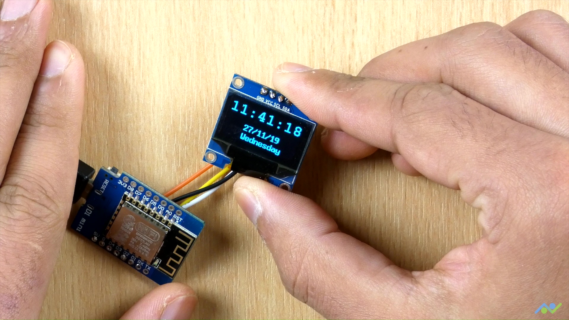
Go over the connections again and ensure you have the ESP8266’s Arduino IDE board support package installed along with the U8g2 library. Once confirmed, connect the Wemos D1 to your computer and select it in the Arduino IDE along with the port to which it is connected. Hit the upload button and wait for the completion of the upload process. When Completed, you should see the time and date information is displayed on the OLED as shown in the image below.
Going Further
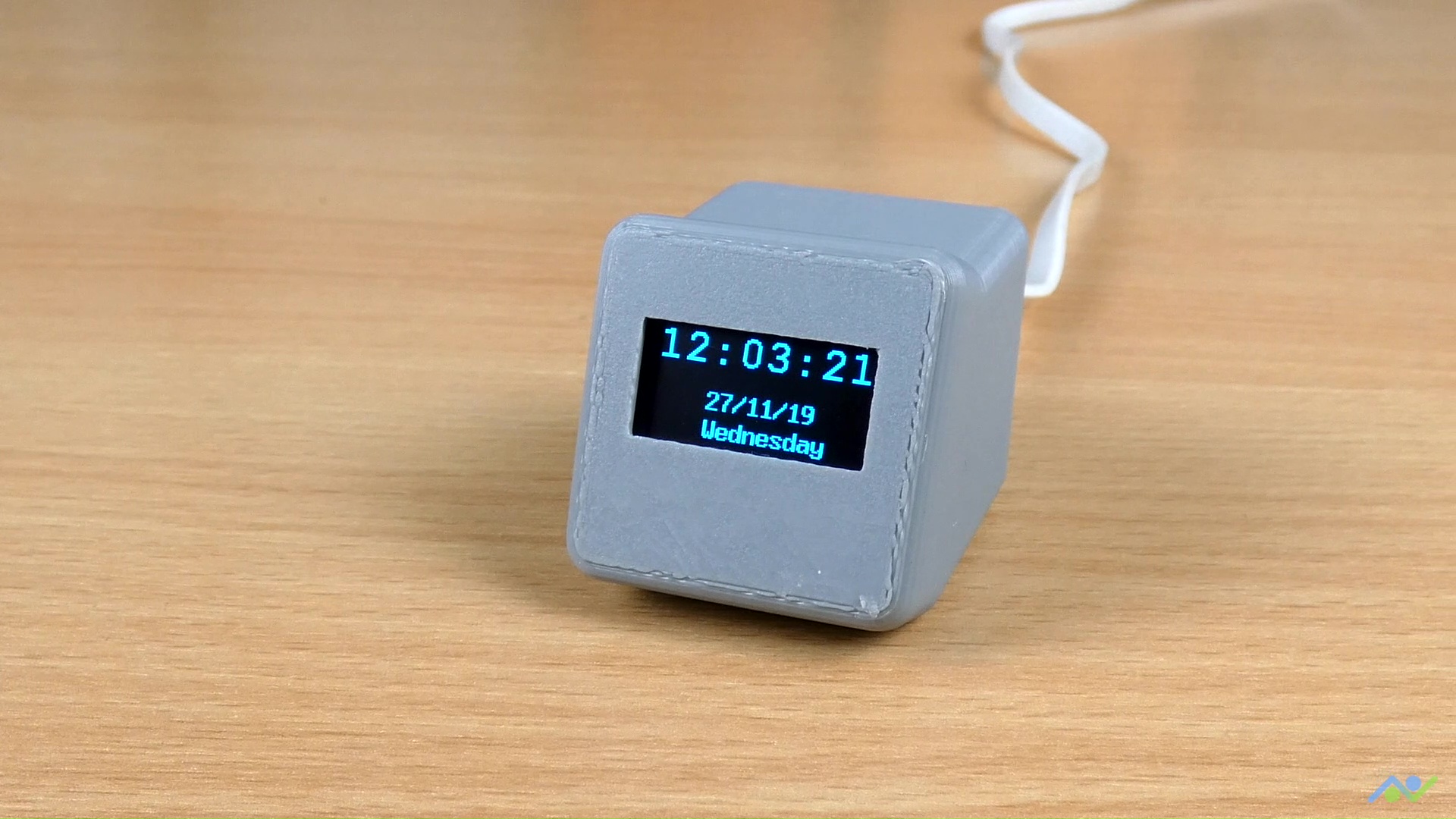
To take things further, one of the quick things you can do is hook up the device into the 3D printed enclosure designed by “BitsandBlobs”. The design and assembly instructions are available on Thingiverse, so all you need to do is to download and print it. After putting it in the 3D printed enclosure, the clock looks like the image below.
That’s it for this tutorial, thanks for reading. Do let me know via the comment section if you built one of these and also let me know if you have any challenges replicating them.


Thanks for this project, I’m very much the novice and new to all things Arduino & co. and these sorts of projects help in the learning journey. This project worked fine except I got “Error” for the day of week.. I’m using an ESP32 / SDD1306 combo. I tried moving “Sunday” to position one and naming it “Case 0” and it all works fine now.. I waited till today today (Monday) to post a reply just to make sure the change was in fact working.
Thanks for your valuable feedback. We are glad that it worked as it should be.
Any idea why it skips a couple seconds?
I had the issue with seconds jumping but just removed them by changing lines 104 and 105 to :-
104 . u8x8.setCursor(3,0)
105 . sprintf(time_output, “%02d:%02d”, localTime->tm_hour, localTime->tm_min);
Thanks for the project. No matter the timezone selected, it shows 2 hours behind actual time. What needs to be modified?
sprintf(time_output, “%02d:%02d:%02d”, localTime->tm_hour+2, localTime->tm_min, localTime->tm_sec);
to fix the 2hrs delay on line 105
Hello! awesome project! has somebody come up with an easy way to convert this time to 12 hour format?
I am very grateful to the author for sharing the “Internet Clock”. The preface to the article is very careful and easy to use. I modified the code to use the esp-01 of the small board. I have successfully tested it on the breadboard. I will find time to do it. Install a 3D printed shell and post my YouTube video
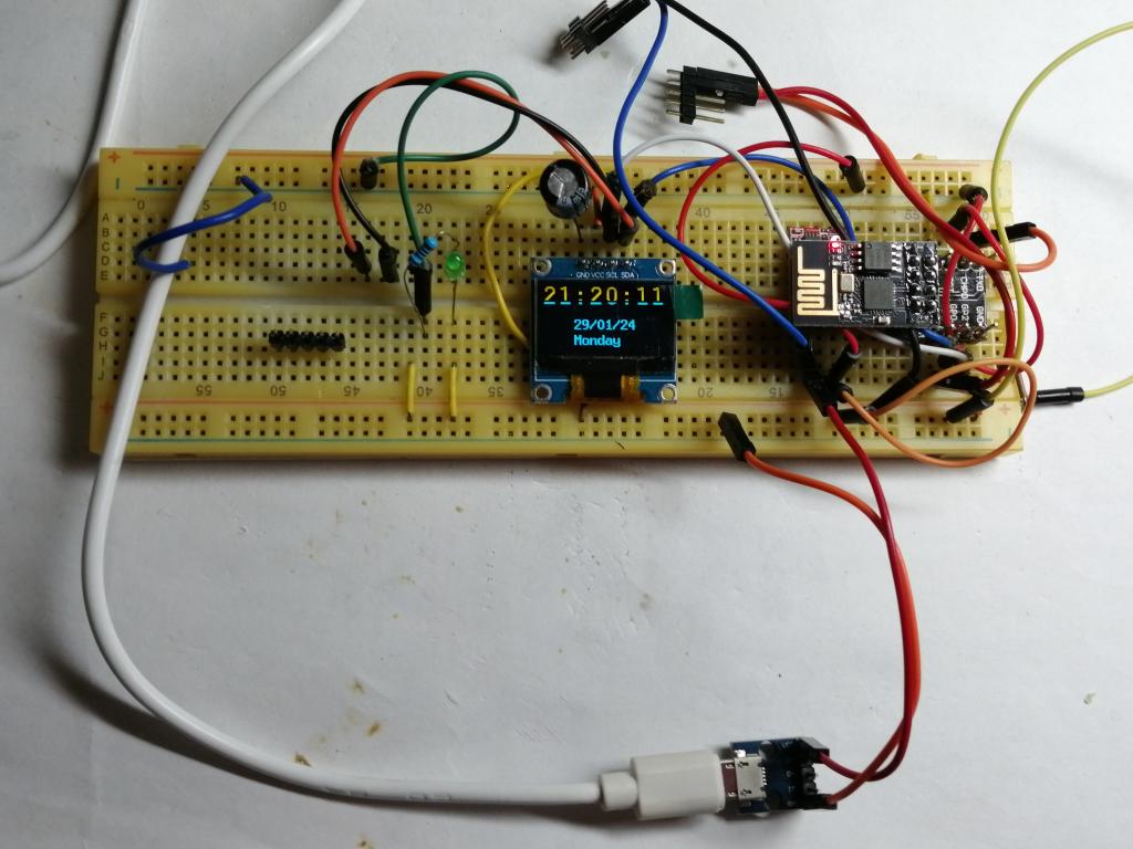
It is Monday, January 29, 2024
If you put the delay about 250-500ms, you are 100% sure you always show up the right seconds displayed on the OLED screen, otherweise every 1000msec you see sometimes some second skipped 1-2-3..5-6-..8..