PHmeter – Arduino pH meter
- Emmanuel Odunlade
- https://twitter.com/emmaodunlade
- emmaodunlade@gmail.com
- 14.503 Views
- medium
- Tested
pH meters are scientific instruments used for measuring the activity and concentration of hydrogen-ions in water-based solutions, with the aim of indicating its acidity or alkalinity expressed as pH values. They find application in water & wastewater treatment, pharmaceuticals, chemicals & petrochemicals, food & beverages, mining, and agricultural processes to mention a few. For today’s tutorial, we will attempt to build an accurate, DIY version of this very useful tool.
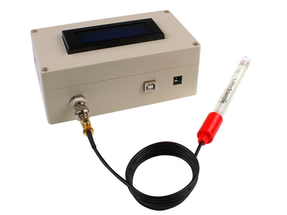
pH meters comprises of majorly a probe and a processing unit which interprets the data from the probe and displays in a human readable format. pHmeter essentially measures the difference in electrical potential between a pH electrode and a reference electrode. As a result of this, pH meters are sometimes referred to as a “potentiometric pH meters”.
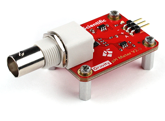
While there are several DIY pHmeter examples on the internet, today’s project will be based on the examples provided by Atlas Scientific. We will use the Atlas Scientific pH probe and their Gravity analog pH meter breakout board. The Gravity analog pH meter breakout board is a fairly accurate low-cost pH metering solution specifically designed for Students / education, Proof of concept developments and pH metering applications requiring moderate accuracy levels. It comes with a BNC port through which it can be connected to the Atlas Scientific pH probe.
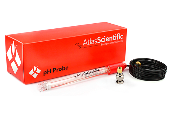
Asides the pH breakout and the probe, we will use an Arduino Uno and a 20×4 LCD display. The Arduino will serve as the brain for the project obtaining the pH level from the probe while the LCD will serve the purpose of providing visual feedback to the users as the value obtained by the Arduino will be displayed on the LCD.
To make the project neat, Atlas Scientific also created a nice enclosure and we will follow the steps outlined by them to create our own.
Ready? let’s jump in.
Required Components
We start by first getting supplies for our build. The following components are needed to build this project;
- Arduino Uno ix 1
- Gravity analog pH sensor x1
- pH probe x1
- 20×4 LCD module
- 158x90x60mm Enclosure
- Mini breadboard
- Jumper wires
- Acrylic sheet (plexiglass)
- 11mm standoffs and screws (comes with the pH sensor) x4
- Resistors 220Ω $ 1kΩ
To reduce the workload associated with searching for the exact components used for this tutorial, I have included links through which each of the components can be bought.
Asides the components, a few tools are required for developing the enclosure, but since that is not so important we will leave it till we get to that stage.
Schematics
The schematics for today’s project is quite straightforward. We will connect the LCD using the 4-pin mode, while we willconnect the signal pin from the PH sensor to an analog pin on the Arduino since it’s output is analog.
Connect the components as shown in the schematics below:
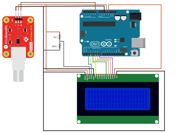
To make the schematics easy to follow, a pin map showing how the components are connected to the Arduino is provided below;
PHmeter – Arduino
+/VCC - 5V
-/GND - GND
A/OUT - A0
LCD – Arduino
K - GND
A - 3.3V
D7 - D7
D6 - D6
D5 - D5
D4 - D4
E - D3
RS - D2
R/W - GND
VSS - GND
VDD - 5V
VO - 5V Via Resistors as voltage dividers
Go over the connections when done to ensure everything is as it should be.
Enclosure Design
With the connections ready, to make the project neat and presentable an enclosure was created. The enclosure is based on the popular abs plastic enclosures and it was modified with drills and other tools so it accommodates the screen and fits perfectly for other projects. A picture of the completed enclosure is displayed in the image below.

To modify the ABS enclosure for the desired neat and clear shape as shown in the picture above, different kind of tools were used including; a Drill, drill bits, drywall cutter bits, files, screwdrivers, benchtop vise, band saw, glue gun and glue stick, soldering iron and solder, digital caliper, ruler. While having these tools makes the process of making the enclosure easier and faster, feel free to use make shift tools that in one way or the other, help achieve the goal of a neat enclosure.
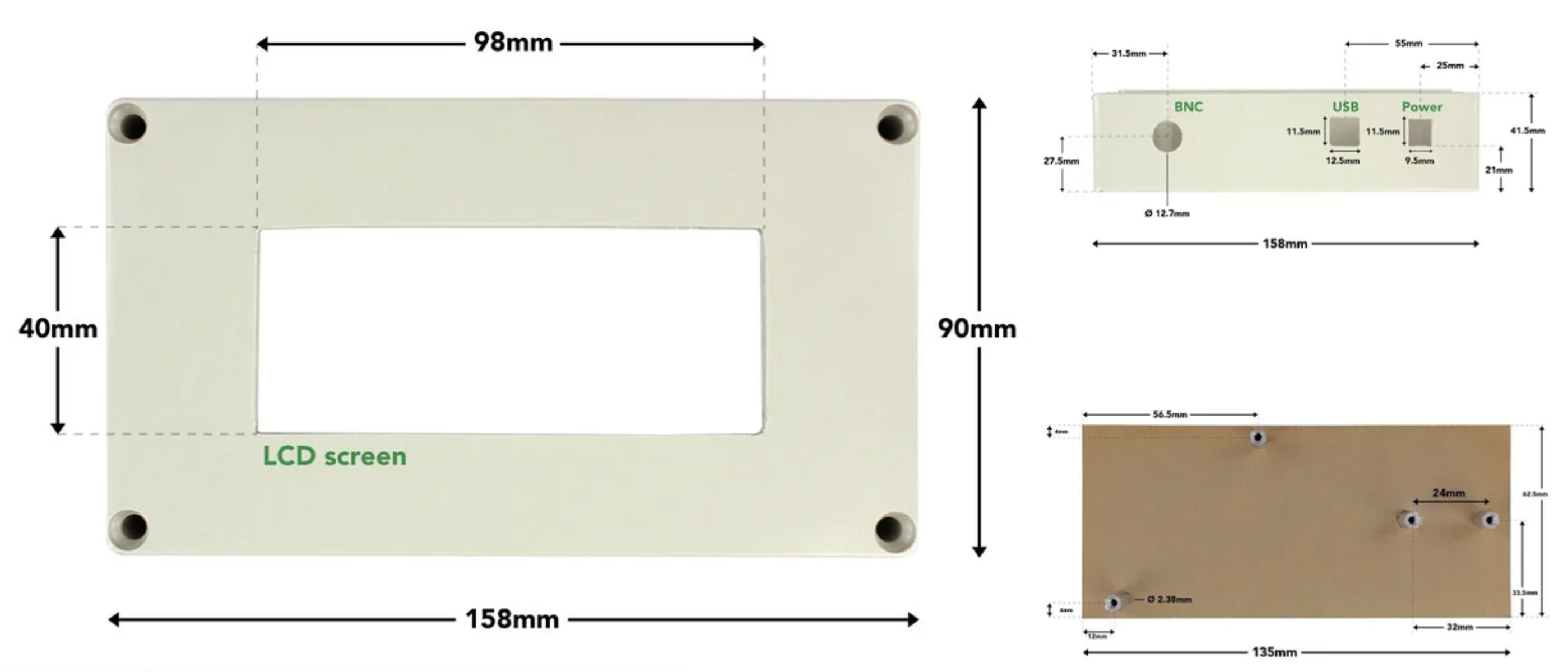
All of the modifications made to the ABS enclosure are based on the diagram below. You may need to zoom in to see the dimensions properly.
You can follow the steps below to achieve this with good precision. Feel free to use other tools/makeshift tools where needed.
Cut opening for the LCD
- The LCD is placed in the top portion (cover) of the enclosure. Center a 98x40mm rectangle on the cover.
- Put the piece in the vise and drill a 3.2mm (1/8″) pilot hole in the rectangle that was marked off.
- Use this pilot hole as the start point for the 3.2mm (1/8″) drywall cutting bit. Since this a small job, we will use the bit on the hand drill rather than a drywall cutting machine. Work on the inside of the rectangle instead of the lines as it may be a bit difficult to cut in a straight manner with this bit on the drill.
- Next, use a hand file to remove the excess material and shape the rectangle to the required size.
Cut openings for BNC connector and Arduino ports
The openings for the BNC connector and Arduino ports are on the side of the bottom portion of the enclosure.
- Using the dimensions provided above, mark the center point for the circle and outlines for the two rectangles.
- Put the piece in the vice and cut the openings. The circular opening is made using drill bits. The rectangular ones are made by following a similar process used to make the opening for the LCD.
Outfit the base plate to mount components
The base plate is used to mount the Arduino, pH sensor and mini breadboard. 6.4mm (1/4″) thick acrylic sheet is used.
- Using a band saw, cut the acrylic sheet to 135×62.5mm.
- Mark off the positions for the four holes as shown. Drill 2.38mm (3/32″) diameter holes. Countersink the holes on one side of the plate to a depth of 3mm and diameter of 4.4mm (11/64″). This is necessary to keep a flat undersurface when the screws are inserted to hold the standoffs.
- Attach the 11mm standoffs using the provided screws. The pH sensor comes with 4 standoffs and screws. Use two of them for the Arduino.
With the enclosure complete, arrange the components inside it such that the set up looks like the image below.

Code
The code for today’s project is quite straightforward. Our tasks as mentioned during the introduction is to collect the pH level using the pH meter and display on the attached LCD.
We will use the Arduino IDE for the development of the code and will use 2 major libraries; the Liquid Crystal Display library and the Atlas gravity sensor library. The liquid crystal display library is used to reduce the amount of work/code that is required to get the Arduino to interact with the LCD, while the Atlas Gravity Sensor Library makes it easy to interface with the PH meter and obtain data. The Liquid Crystal Library usually comes with the Arduino IDE but just in case it didn’t, you can always install it via the Arduino Library manager. The Atlas Gravity Sensor library, on the other hand, needs to be installed manually, as such, you will need to download it from the attached link, unzip it and copy it’s content into the Arduino Library folder. The library folder is usually in the same folder as your Arduino Sketches.
With the libraries installed, we can now proceed to writing the code.
The sketch starts by including the libraries that will be used.
#include "ph_grav.h"                                  //header file for Atlas Scientific gravity pHsensor
#include "LiquidCrystal.h"                            //header file for liquid crystal display (lcd)
Next, we declare some of the variables that will be used during the code, declare the analog pin of the Arduino to which the PH sensor analog output pin is connected, and create instances of both the Atlas Gravity Sensor Library and the Liquid Crystal Library.
String inputstring = "";                              //a string to hold incoming data from the PC
boolean input_string_complete = false;                //a flag to indicate have we received all the data from the PC
char inputstring_array[10];                           //a char array needed for string parsing
Gravity_pH pH = A0;                                   //assign analog pin A0 of Arduino to class Gravity_pH. connect output of pH sensor to pin A0
LiquidCrystal pH_lcd(2, 3, 4, 5, 6, 7);               //make a variable pH_lcd and assign arduino digital pins to lcd pins (2 -> RS, 3 -> E, 4 to 7 -> D4 to D7)
With those done, we proceed to to the void setup() function. We start the function by initializing serial communication which will is used for debug purposes, and the LCD display on which a splash/initialization screen is displayed.
void setup() {
  Serial.begin(9600);                                 //enable serial port
  pH_lcd.begin(20, 4);                                //start lcd interface and define lcd size (20 columns and 4 rows)
  pH_lcd.setCursor(0,0);                              //place cursor on screen at column 1, row 1
  pH_lcd.print("--------------------");               //display characters
  pH_lcd.setCursor(0,3);                              //place cursor on screen at column 1, row 4
  pH_lcd.print("--------------------");               //display characters
  pH_lcd.setCursor(5, 1);                             //place cursor on screen at column 6, row 2
  pH_lcd.print("pH Reading");                         //display "pH Reading"
lastly the PH meter is initialized and the control commands for calibration are displayed on the serial monitor.
if (pH.begin()) { Serial.println("Loaded EEPROM");}
  Serial.println(F("Use commands \"CAL,4\", \"CAL,7\", and \"CAL,10\" to calibrate the circuit to those respective values"));
  Serial.println(F("Use command \"CAL,CLEAR\" to clear the calibration"));
 }
Up next is the void loop() function.
The void loop function is quite straight forward. We start by checking if any calibration parameter has been received over the serial monitor. If yes, the data is parsed as an argument into the parse_cmd function where it is used to set the level of calibration required.
void loop() {

  if (input_string_complete == true) {                //check if data received
    inputstring.toCharArray(inputstring_array, 30);   //convert the string to a char array
    parse_cmd(inputstring_array);                     //send data to pars_cmd function
    input_string_complete = false;                    //reset the flag used to tell if we have received a completed string from the PC
    inputstring = "";                                 //clear the string
  }
Next, the PH level is obtained from the PHmeter using the ph.read_ph() function. The values obtained is then displayed on the serial monitor and on the LCD.
  Serial.println(pH.read_ph());                       //output pH reading to serial monitor
  pH_lcd.setCursor(8, 2);                             //place cursor on screen at column 9, row 3
  pH_lcd.print(pH.read_ph());                         //output pH to lcd
  delay(1000);
}
Other parts of the code are the serialEvent() function which is used to obtain user input from the Serial Monitor, and the parse_cmd() function which takes in the data from the serial port and uses it to set the calibration level of the PHmeter.
void serialEvent() {                                  //if the hardware serial port_0 receives a char
  inputstring = Serial.readStringUntil(13);           //read the string until we see a <CR>
  input_string_complete = true;                       //set the flag used to tell if we have received a completed string from the PC
}

void parse_cmd(char* string) {                      //For calling calibration functions
  strupr(string);                                   //convert input string to uppercase

  if (strcmp(string, "CAL,4") == 0) {               //compare user input string with CAL,4 and if they match, proceed
    pH.cal_low();                                   //call function for low point calibration
    Serial.println("LOW CALIBRATED");
  }
  else if (strcmp(string, "CAL,7") == 0) {          //compare user input string with CAL,7 and if they match, proceed
    pH.cal_mid();                                   //call function for midpoint calibration
    Serial.println("MID CALIBRATED");
  }
  else if (strcmp(string, "CAL,10") == 0) {         //compare user input string with CAL,10 and if they match, proceed
    pH.cal_high();                                  //call function for highpoint calibration
    Serial.println("HIGH CALIBRATED");
  }
  else if (strcmp(string, "CAL,CLEAR") == 0) {      //compare user input string with CAL,CLEAR and if they match, proceed
    pH.cal_clear();                                 //call function for clearing calibration
    Serial.println("CALIBRATION CLEARED");
  }
}
The complete code for the project is provided below and also attached under the download section.
/*
Once uploaded, open the serial monitor, set the baud rate to 9600 and append "Carriage return"
The code allows the user to observe real time pH readings as well as calibrate the sensor.
One, two or three-point calibration can be done.

Calibration commands:
 low-point: "cal,4"
 mid-point: "cal,7"
 high-point: "cal,10"
 clear calibration: "cal,clear"
*/

#include "ph_grav.h"                                  //header file for Atlas Scientific gravity pH sensor
#include "LiquidCrystal.h"                            //header file for liquid crystal display (lcd)

String inputstring = "";                              //a string to hold incoming data from the PC
boolean input_string_complete = false;                //a flag to indicate have we received all the data from the PC
char inputstring_array[10];                           //a char array needed for string parsing
Gravity_pH pH = A0;                                   //assign analog pin A0 of Arduino to class Gravity_pH. connect output of pH sensor to pin A0
LiquidCrystal pH_lcd(2, 3, 4, 5, 6, 7);               //make a variable pH_lcd and assign arduino digital pins to lcd pins (2 -> RS, 3 -> E, 4 to 7 -> D4 to D7)


void setup() {
  Serial.begin(9600);                                 //enable serial port
  pH_lcd.begin(20, 4);                                //start lcd interface and define lcd size (20 columns and 4 rows)
  pH_lcd.setCursor(0,0);                              //place cursor on screen at column 1, row 1
  pH_lcd.print("--------------------");               //display characters
  pH_lcd.setCursor(0,3);                              //place cursor on screen at column 1, row 4
  pH_lcd.print("--------------------");               //display characters
  pH_lcd.setCursor(5, 1);                             //place cursor on screen at column 6, row 2
  pH_lcd.print("pH Reading");                         //display "pH Reading"
  if (pH.begin()) { Serial.println("Loaded EEPROM");}
  Serial.println(F("Use commands \"CAL,4\", \"CAL,7\", and \"CAL,10\" to calibrate the circuit to those respective values"));
  Serial.println(F("Use command \"CAL,CLEAR\" to clear the calibration"));
 }


void loop() {

  if (input_string_complete == true) {                //check if data received
    inputstring.toCharArray(inputstring_array, 30);   //convert the string to a char array
    parse_cmd(inputstring_array);                     //send data to pars_cmd function
    input_string_complete = false;                    //reset the flag used to tell if we have received a completed string from the PC
    inputstring = "";                                 //clear the string
  }
  Serial.println(pH.read_ph());                       //output pH reading to serial monitor
  pH_lcd.setCursor(8, 2);                             //place cursor on screen at column 9, row 3
  pH_lcd.print(pH.read_ph());                         //output pH to lcd
  delay(1000);
}

void serialEvent() {                                  //if the hardware serial port_0 receives a char
  inputstring = Serial.readStringUntil(13);           //read the string until we see a <CR>
  input_string_complete = true;                       //set the flag used to tell if we have received a completed string from the PC
}

void parse_cmd(char* string) {                      //For calling calibration functions
  strupr(string);                                   //convert input string to uppercase

  if (strcmp(string, "CAL,4") == 0) {               //compare user input string with CAL,4 and if they match, proceed
    pH.cal_low();                                   //call function for low point calibration
    Serial.println("LOW CALIBRATED");
  }
  else if (strcmp(string, "CAL,7") == 0) {          //compare user input string with CAL,7 and if they match, proceed
    pH.cal_mid();                                   //call function for midpoint calibration
    Serial.println("MID CALIBRATED");
  }
  else if (strcmp(string, "CAL,10") == 0) {         //compare user input string with CAL,10 and if they match, proceed
    pH.cal_high();                                  //call function for highpoint calibration
    Serial.println("HIGH CALIBRATED");
  }
  else if (strcmp(string, "CAL,CLEAR") == 0) {      //compare user input string with CAL,CLEAR and if they match, proceed
    pH.cal_clear();                                 //call function for clearing calibration
    Serial.println("CALIBRATION CLEARED");
  }
}
Calibration
To ensure the accuracy of the results from the pH meter, there is a need to accurately calibrate the device. pH meters are calibrated across 3 levels; 4, 7, and 10 using standard buffer solutions that already exists at that PH level. These standard solutions are sometimes provided by the sellers of the PH sensor but when not provided, you can always get them from your local chemical stores.
To calibrate the meter, upload the sketch we developed above to your Arduino. Take some time to ensure the components are properly connected before doing this. When sketch upload is complete, open the serial monitor, based on our code the serial monitor will prompt you to enter the calibration values, with samples showing how to enter them correctly. When at this stage, follow the steps below to calibrate the meter with the three buffer solutions.
- Remove the soaker bottle and rinse the pH probe
- Start with the standard buffer solution for pH4. Pour some of the pH 4 solution, enough to cover the probe, into a cup.
- Place the probe in the cup and stir it around to remove trapped air. Observe the readings on the serial monitor and leave the probe there till the readings stabilize.
- When the readings become stable, enter the command cal,4 into the serial monitor to instruct it to save that value as the calibration value for pH4.
- Repeat these steps with the pH7 and pH10 solutions, ensuring you rinse the probe as you move from one solution to the other.
With these done, the pH meter is now calibrated and should be able to give the correct pH level for any solution the probe is tested with. The calibration values are saved on the Arduino’s EEPROM so they are not lost when the meter is disconnected from power. This makes calibration not necessary before every use but you should re-caliberate the system again after some time, so you can always enter the cal,clear command on the serial monitor to clear the previous stored calibration values and repeat the steps explained above.
Demo
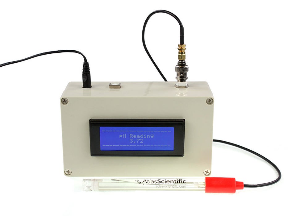
With the code uploaded and calibration done, you can now go ahead and dip the probe into any solution you desire and you should see the pH value displayed on the LCD like shown in the image below.
The accuracy of the pHmeter varies with temperature, as such, it is important to note that the sensor used in this project has an accuracy of +/- 0.2% and that the pH meter will operate at this accuracy level when the temperature range is between 7 – 46°C. Outside of this range, the meter will have to be modified to compensate.
Going forward, while the scope of this project is limited to pH value, you can choose to add several other sensors to make the project more useful. A good example of sensors that could be added for more value include temperature and humidity sensors.
That’s it for this tutorial, thanks for reading. Is there something I missed out, or you have one issue or the other implementing the project? feel free to reach out to me via the comment section.





I like projects to be professionally placed into an enclosure, like you have done here. I plan to contribute some projects this year. I too am a designer, and we need more projects to be engineered around a box enclosure.
I built one. The PH reading jumps around a lot. .I rebuilt it and recalibrated and still the same.