Type K Thermocouple Sensor Amplifier Arduino Shield
- Rajkumar Sharma
- 4.469 Views
- easy
- Tested
- SKU: EL98458
- Quote Now
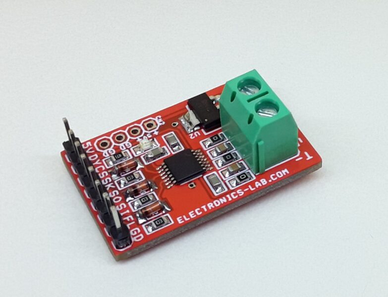
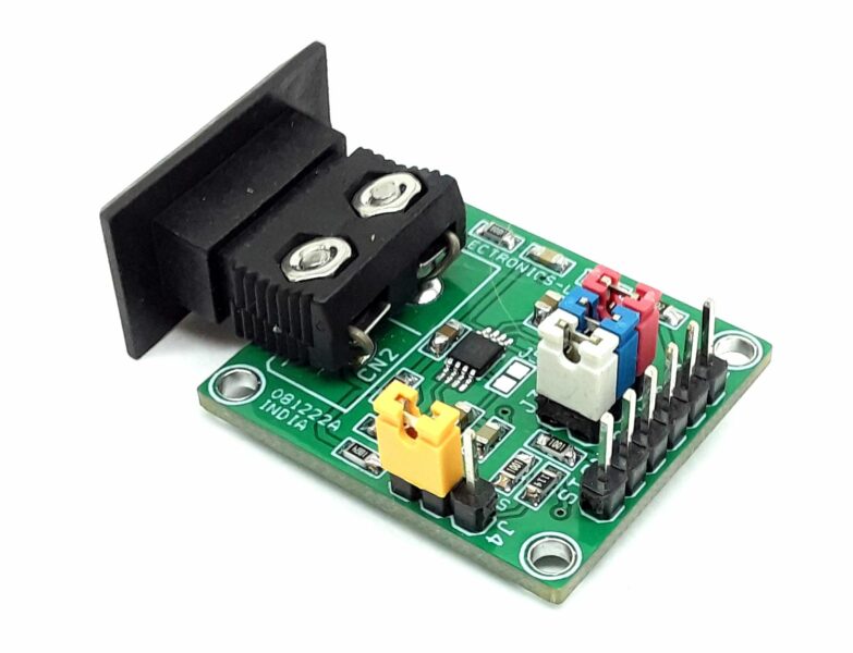
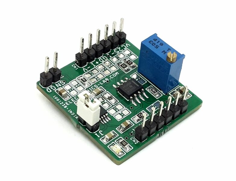
This is a Type K Thermocouple Sensor Amplifier Arduino Shield that enables an Arduino board to acquire temperatures from a thermocouple of type K. The shield works with a single supply and takes 5V DC from the Arduino board, the output of the circuit is 0 to 4V DC for 0-degree centigrade to 400C. The output of the amplifier is connected to the A0 analog pin of Arduino. A typical application of thermocouples is in boilers, soldering stations, and heaters. Also, 3D printers rely on thermocouples to measure the extruder temperature.
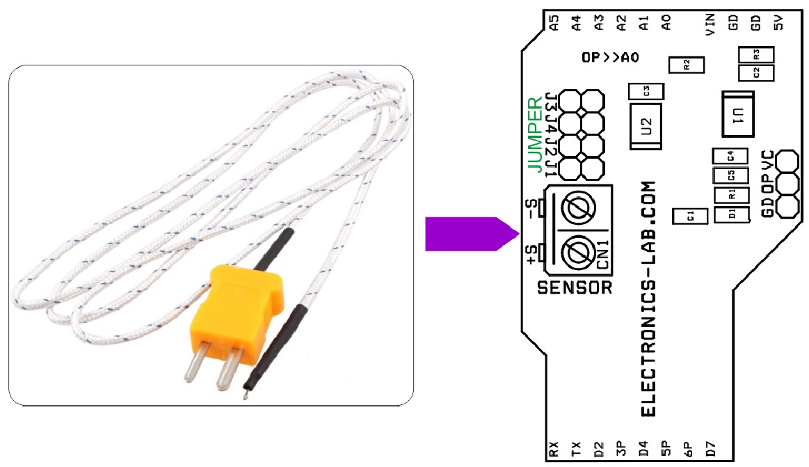
The K thermocouple has usually two wires, made of Alumel and Chromel that need to be connected with special care: no solder, just use a mechanical connection, therefore it is advisable to use special connectors available for thermocouples.
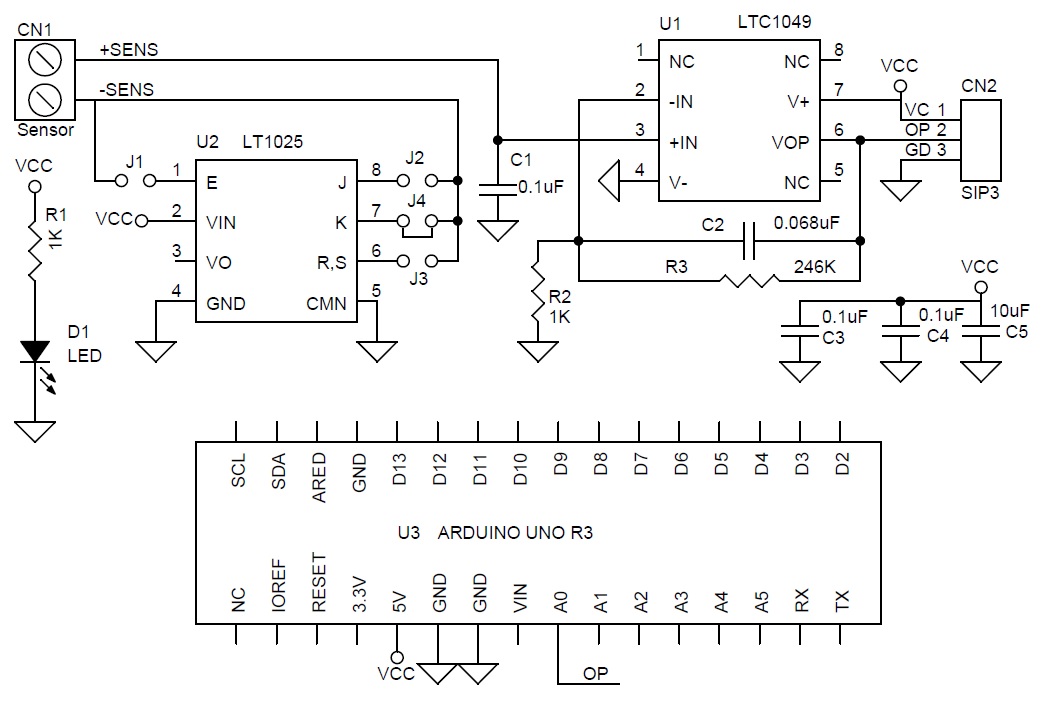
The circuit is built using LTC1049 op-amp and Thermocouple Cold Junction Compensator chip LTC1025. The board also supports other sensors like Type E, J, R, S, and T, however I have tested this circuit with Type K Sensor, jumpers are provided to use, and select other types of sensors.
The LTC1049 is a high performance, low power zero-drift operational amplifier. The two sample-and-hold capacitors usually required externally by other chopper stabilized amplifiers are integrated on the chip. Further, the LTC1049 offers superior DC and AC performance with a nominal supply current of only 200μA. The LTC1049 has a typical offset voltage of 2μV, drift of 0.02μV/°C, 0.1Hz to 10Hz input noise voltage of 3μVP-P and typical voltage gain of 160dB. The slew rate is 0.8V/μs with a gain-bandwidth product of 0.8MHz.
The LT®1025 is a micropower thermocouple cold junction compensator for use with type E, J, K, R, S, and T thermocouples. It utilizes wafer level and post-package trimming to achieve 0.5°C initial accuracy. Special curvature correction circuitry is used to match the “bow” found in all thermocouples so that accurate cold junction compensation is maintained over a wider temperature range. The LT1025 will operate with a supply voltage from 4V to 36V. The typical supply current is 80mA, resulting in less than 0.1°C internal temperature rise for supply voltages under 10V. A 10mV/°C output is available at low impedance, in addition to the direct thermocouple voltages of 60.9mV/°C (E), 51.7mV/°C (J), 40.3mV/°C (K, T) and 5.95mV/°C (R, S). All outputs are essentially independent of power supply voltage
Features
- Supply 5V DC
- Thermocouple Sensor: Type K
- Output 0 to 4V DC
- Temperature Sensing range 0 to 400 Degree Centigrade
- PCB dimensions: 31.75 x 51.12mm
Schematic
Parts List
Connections
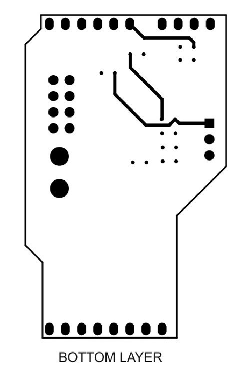
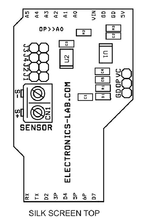
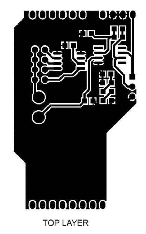
Gerber View
Sample Code
/*
  AnalogReadSerial

  Reads an analog input on pin 0, prints the result to the Serial Monitor.
  Graphical representation is available using Serial Plotter (Tools > Serial Plotter menu).
  Attach the center pin of a potentiometer to pin A0, and the outside pins to +5V and ground.

  This example code is in the public domain.

  http://www.arduino.cc/en/Tutorial/AnalogReadSerial
*/

// the setup routine runs once when you press reset:
void setup() {
  // initialize serial communication at 9600 bits per second:
  Serial.begin(9600);
}

// the loop routine runs over and over again forever:
void loop() {
  // read the input on analog pin 0:
  int sensorValue = analogRead(A0);
  // print out the value you read:
  Serial.println(sensorValue);
  delay(1);        // delay in between reads for stability
}


