Using ESP32’s Flash Memory for data storage
- Nick Koumaris
- http://educ8s.tv
- info@educ8s.tv
- 65.283 Views
- moderate
- Tested
The ESP32 has about 4MB of internal flash memory and since the data stored within the flash memory is retained even when power is recycled, it becomes super useful for applications where you need to keep certain amount of data even after power off. For today’s tutorial, we will learn how to read and write data to the ESP32’s Flash Memory.
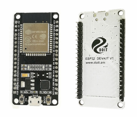
The flash memory is similar to the EEPROM memory which is common in most microcontrollers. It is a Non-Volatile memory which means that the data stored, remain even when the ESP undergoes a reset or power is cycled. This can be very useful in applications where you need to store particular device settings, remember the last state of a particular variable, or store some important runtime data for later use, etc. To give an example, say a piece of equipment being controlled by the ESP32 was ON when power was cut, in most cases, the equipment will stay OFF when power returns depending on the set parameters but with the help of Flash memory, the system can be programmed to return to the last state that was stored.
As cool as non-volatility is, flash memories, however, have a downside which limits their applications; they usually have a fixed number of write operations. Thus the data in flash memories should only be overwritten when it has been compared and a difference has been established.
To demonstrate the use and capabilities of the flash memory, we will build a dimmer circuit in which a potentiometer is used to vary the brightness of an LED and the system is required to remember the brightness level after a reset. Alongside the use of the Flash memory for storage, at the end of this tutorial, you will know how to use an analog sensor with the ESP32 and how PWM works with it.
Required components
The following components are required for this project;
- ESP32 DOIT DEVKIT V1 Board
- Breadboard
- 5mm LED
- 220 Ohm resistor
- 10k Potentiometer
- Jumper wires
While the project is based on the DOIT’s ESP32 DevKit V1 board, it should also work with any of the other ESP32 based development boards.
Schematics
Connect the components as shown in the schematics below.
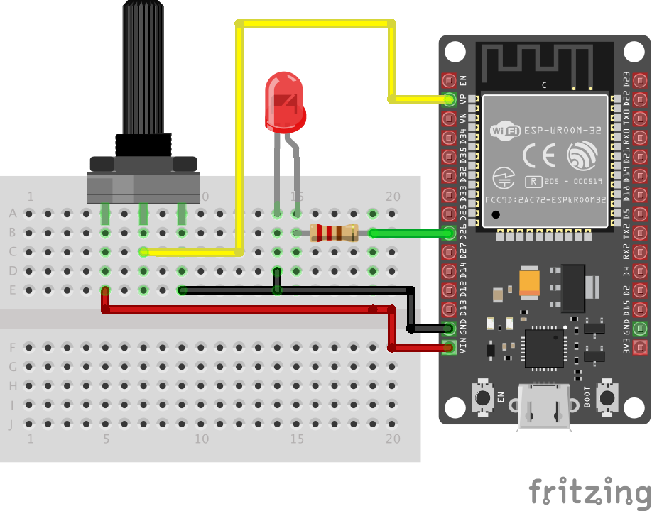
Unlike ESP8266, the ESP32 has 18 analog pins to which the potentiometer can be connected, so you can change the pins as desired. Also, all the 36 GPIO pins on the ESP32 board are PWM enabled, so the LED can be connected to any of the GPIO pins.
Code
The code for this project is a little bit tricky. The algorithm performs some simple tasks, such as it simply reads the analog value on the potentiometer, it use it to vary the brightness of the LED and it stores the value in the flash memory, such that the next time the program runs without input from the potentiometer, it uses the last value stored in the flash memory.
As mentioned earlier the Flash memory is a variant of the EEPROM, so it may not be strange that we will use the ESP32 EEPROM library for this project. The library is automatically installed on the Arduino IDE when you install the board files for the ESP32. Its usage is the same as using the Arduino EEPROM library with few differences in function declarations. The EEPROM Library will enable us to use up to 512 bytes of the flash memory. This means we will have 512 different addresses and we will be able to save data between 0 and 255 in each of the addresses. There are three main functions from the EEPROM library associated with storage and retrieval of data;
- EEPROM.write(address, value)
- EEPROM.commit()
- EEPROM.read(address)
To write data to a memory address, the EEPROM.write() function is called with the data and the address to which it should be written supplied as arguments. To complete the data write, the EEPROM.commit() function should be called. The commit function checks to confirm that the data indicated in the write() function is different from what is currently there before committing it to the flash memory. With the finite nature of the number of times data can be written to the Flash memory, the commit() function helps to reduce unnecessary write operations to keep the number of write operations low.
The read() function, on the other hand, is used to retrieve information from the address that is specified as the argument for the function. These three functions will be at the center of today’s project.
We start as usual, by including the libraries required for the code, which in this case is just the EEPROM library.
// include library to read and write from flash memory
#include <EEPROM.h>
Next, we specify the pins of the ESP32 to which the other components are connected and we declare the variables that will be used to store data in the code. One of the downsides of the ESP32 is that the support level is not yet as high as its available for other boards. To write values to a PWM pin on an arduino board, one need just to call the analogWrite() function but this function is not available for the ESP32, thus the variables; freq, ledchannel and resolution will be used to achieve the same tasks as the analogWrite() function.
//GPIO pin declarations
#define ANALOG_PIN_0 36
#define LED_PIN 26

// PMW Parameters
int freq = 5000;
int ledChannel = 0;
int resolution = 8;
int dutyCycle;


// Variables to store the potentiometer;s value and the current state of the LED
int analog_value;
int ledState = 0;         // the current state of the output pin we start with 0
Next, we write the void setup() function. We start the function by initializing serial communication and communications with the EEPROM.
void setup() {
  Serial.begin(115200);
  // initialize EEPROM with predefined size
  EEPROM.begin(EEPROM_SIZE);
Next, we use the ledcSetup() function to setup the properties of the PWM channel with the resolution, frequency and channel(ledChannel) as arguments, after which we attach the pin to which the LED is connected to the configured PWM channel. The ADC on the ESP32 has a resolution of 10bits and by setting the resolution of the PWM channel to 8bits, we make its values similar to that of the Arduino.
ledcSetup(ledChannel, freq, resolution);
ledcAttachPin(LED_PIN, ledChannel);
To wrap up the voidsetup() function, we read the EEPPROM to check if there was a previous value for the brightness of the LED and using the EEPROM.read() function and use the ledcWrite() (which is our equivalent of the analogWrite() function) to set the brightness of the LED.
// read the last LED state from flash memory
ledState = EEPROM.read(0);
ledcWrite(ledChannel, ledState);
Next, we write the void loop() function. The function simply checks the input value from the potentiometer, compares it with the last value stored and if there is a difference, the brightness of the LED is set to the new value and the flash memory is updated using the EEPROM commands.
We start the loop() function by reading the analog value from the potentiometer.
analog_value = analogRead(ANALOG_PIN_0);
Since the ADC is by default, at 10bits, we map the value to that of 8bits to ensure it tallies with the PWM resolution we declared earlier.
dutyCycle = map(analog_value, 0, 4095, 0, 255);
Next, we check if there is a difference between the last value and the current one and if there is, we set the brightness of the LED to this new value and update the flash memory with the EEPROM.write() command followed by the commit function.
Serial.println("value changed");
   ledcWrite(ledChannel, dutyCycle);
   ledState = dutyCycle;
   // save the brightness value in flash memory
   EEPROM.write(0, ledState);
   EEPROM.commit();
   Serial.println("New value saved in flash memory");
The complete code is available below and also attached under the download section of the tutorial.
// include library to read and write from flash memory
#include <EEPROM.h>

// define the number of bytes you want to access
#define EEPROM_SIZE 1

//GPIO pin declarations
#define ANALOG_PIN_0 36
#define LED_PIN 26

// PMW Parameters
int freq = 5000;
int ledChannel = 0;
int resolution = 8;
int dutyCycle;

int analog_value;
int ledState = 0;

void setup() {
  Serial.begin(115200);
  // initialize EEPROM with predefined size
  EEPROM.begin(EEPROM_SIZE);

  ledcSetup(ledChannel, freq, resolution);
  ledcAttachPin(LED_PIN, ledChannel);

  // read the last brightness level from flash memory
  ledState = EEPROM.read(0);
  ledcWrite(ledChannel, ledState);
}

void loop() {
  // read the potvalue into a local variable:
 analog_value = analogRead(ANALOG_PIN_0);
 dutyCycle = map(analog_value, 0, 4095, 0, 255);
 if (dutyCycle != ledState)
 {
    Serial.println("value changed");
    ledcWrite(ledChannel, dutyCycle);
    ledState = dutyCycle;
    // save the brightness level in flash memory
    EEPROM.write(0, ledState);
    EEPROM.commit();
    Serial.println("level saved in flash memory");
  }
}
Demo
Ensure the components are connected as described under the schematics section and if you made any changes in pin configurations, ensure the code is updated to reflect them. With this done, connect your DOIT ESP32 DevKit to your PC and upload the code. You should see the brightness of the LED vary as you turn the knob of the potentiometer. Set the Potentiometer to a particular recognizable brightness level, then unplug the system. The device will retain the last saved value and set the brightness of the LED to that value once power is connected again.
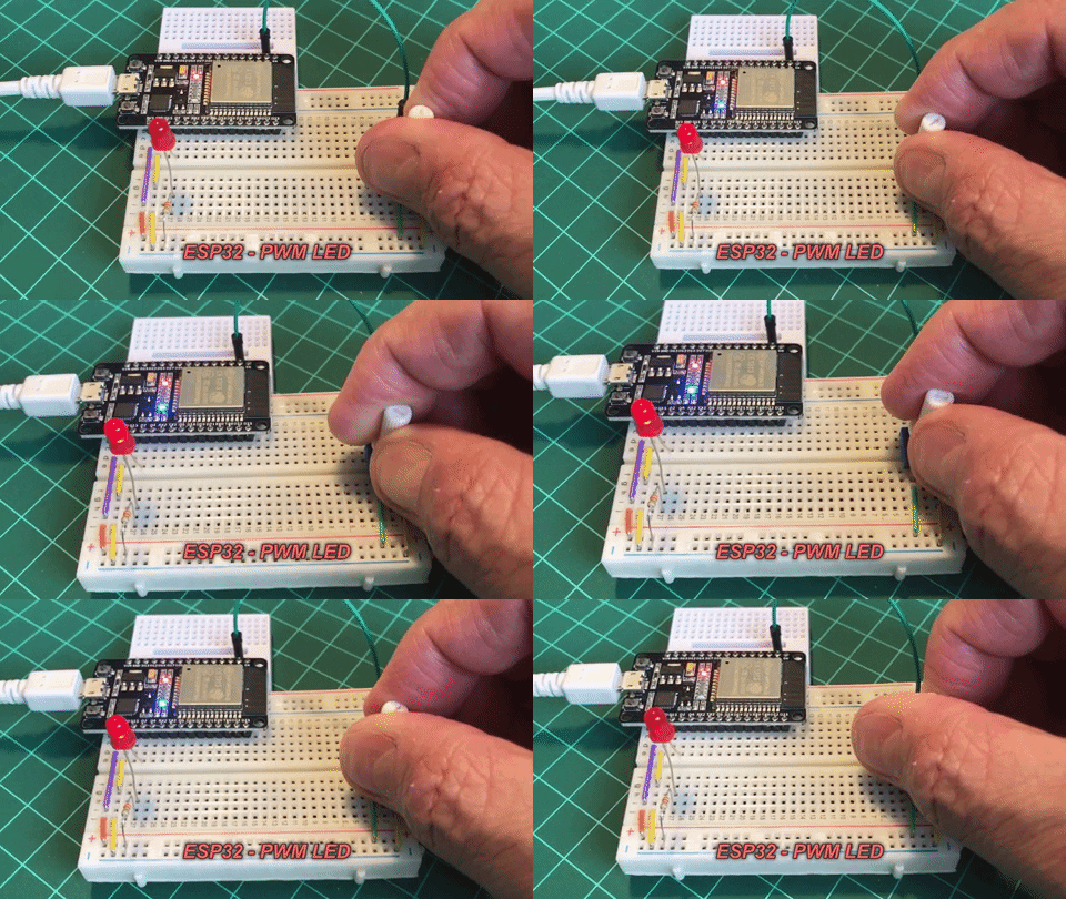
While this is a simple example, this can be used for more useful tasks in a more complex project with the same exact commands.
That’s it for today’s tutorial. Feel free to reach me via the comment section if you have any questions or need any clarification as regards this tutorial.


I cannot find a date on this article, to see how current the info is about the hardware and software. Technology evolves fast.
This is published on Jun 1, 2019
I don’t understand, what amount of kB can I store.