100MHz frequency counter with PIC16F628A – LCD Display
- Hristo
- http://diyfan.blogspot.com
- xristost@yahoo.com
- 124.991 Views
- medium
- Tested
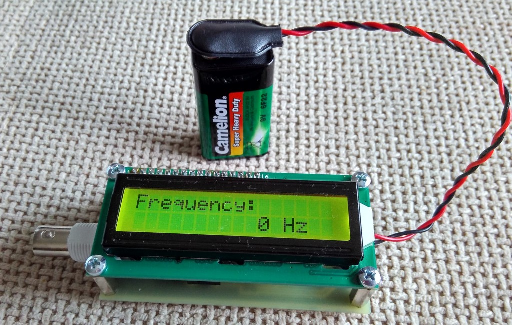
This project shows how to build a very simple yet very useful tool that every DIY enthusiast should have in his lab: a 100MHz+ frequency counter.
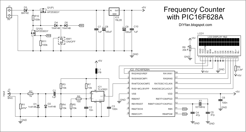
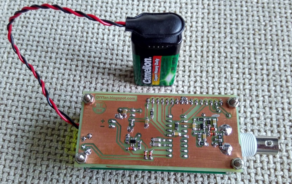
The schematic is fairly simple and straightforward and uses a PIC16F628A microcontroller for measuring frequency and a high speed comparator for signal amplification and conditioning.
The microcontroller uses its internal 4MHz oscillator for the CPU clock. Timer1 uses an external crystal resonator (watch crystal) with 32768Hz frequency for setting the 1 second time base.
Timer0 is used to count the input signal at pin RA4.
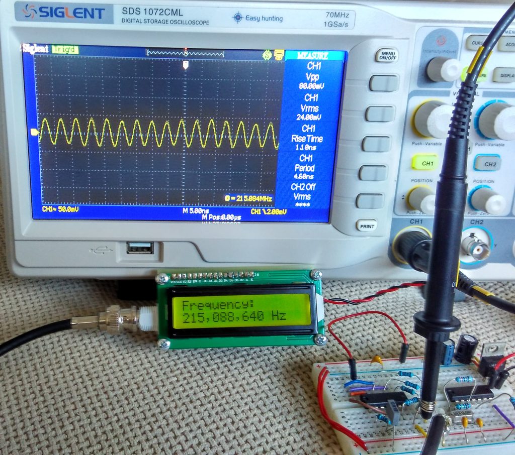
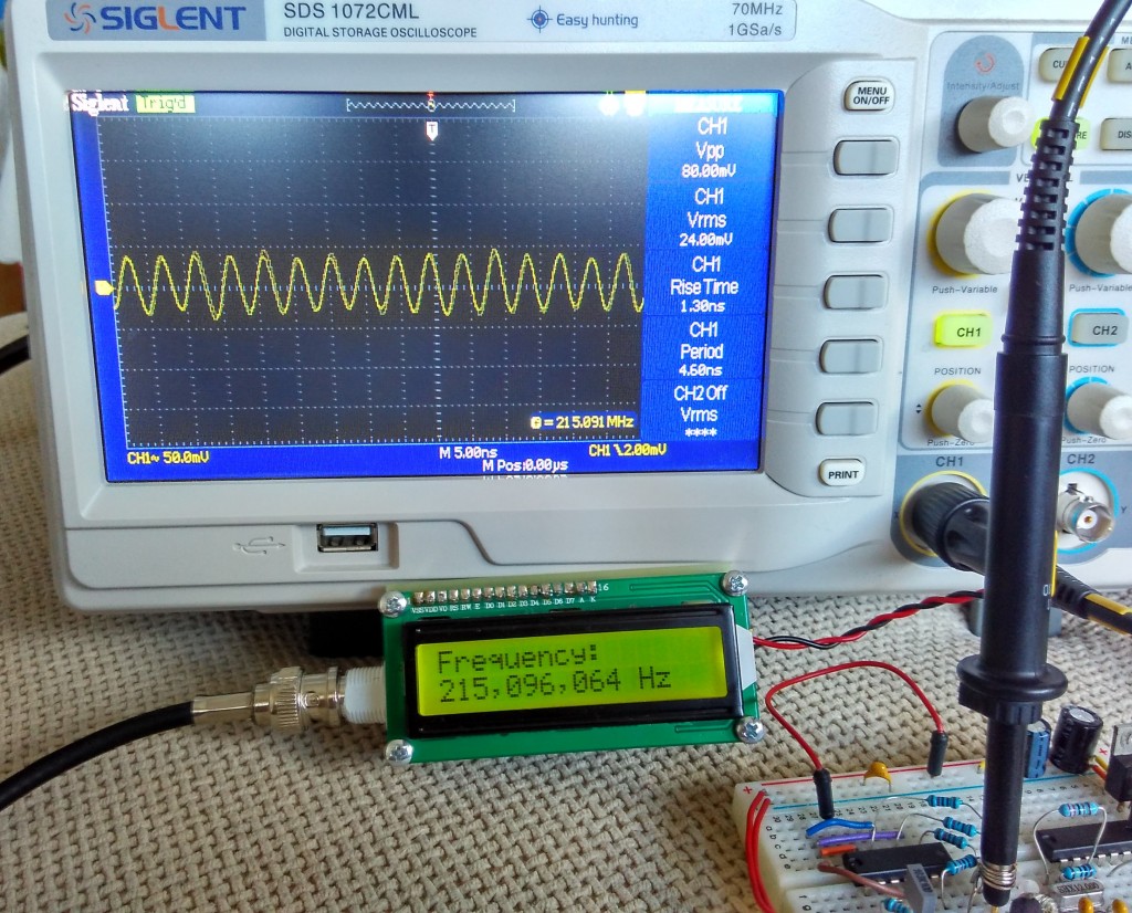
The max frequency of Timer0 is 1/4 of the CPU clock which is 1MHz, but there is internal prescaler and it can be set from 1 to 256. In theory this can allow the input signal to be up to 256MHz. On the other hand, in the datasheet of 16F628A there is a requirement for the input pulse at RA4 to be with minimum width of 10ns which is 100MHz frequency. So the maximum frequency can be between 100Mhz and 256MHz. I checked with two different PIC16F628A and they easily go over 200Mhz barrier.
In order to achieve the maximum possible resolution, the input signal is probed for 0.125 seconds and the prescaler value is computed accordingly. This way when input frequency is below 1Mhz the resolution will be 1Hz.
The most important part for the accuracy of the frequency counter is the time base setting circuit – crystal resonator X1 and capacitors C4 and C5. C4 and C5 values can be between 33pF and 62pF and the crystal frequency can be fine tuned with them.
The input of the schematic is feed through a high speed comparator. In order to switch with 100+ Mhz frequency the comparator must have propagation delay bellow 5ns. In this schematic I used Texas Instruments TLV3501 with 4.5ns delay. This was cheapest high speed comparator I was able to find (2.5 euro).
The two inputs of the comparator are set at about 1/2 of power supply voltage with 15-25mV difference between them so any AC signal with higher voltage will start switching the comparator.
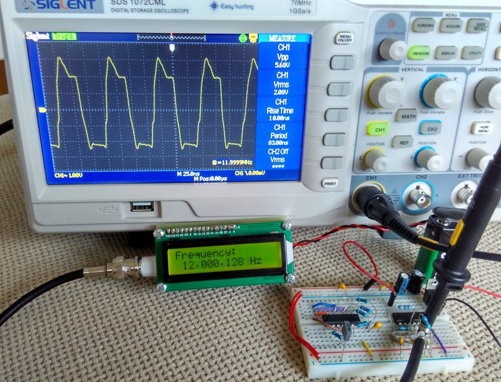
If there isn’t input signal the output of the comparator stays low. If we connect a signal source to the positive input, when the signal goes over +20mV the comparator switches high (5V), when signal goes bellow +20mV comparator switches back to 0V. So whatever signal we fed to the input, the output is square wave 0V-5V with the same frequency as the original signal.
The output of the comparator is fed directly to the RA4 pin of the microcontroller.
The input is protected with 1k resistor and two diodes limiting the voltage to ±0.7 V. The input impedance for low frequencies is equal to R1 – 47k. For VHF range maybe it is good idea to replace it with 50 Ohm value.
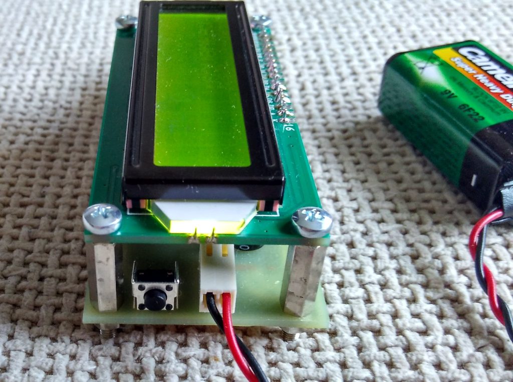
The schematic can be powered by 9V battery or any other DC voltage from 7V to 15-20V. LM78L05 or LM2931-5.0 IC is used for regulating the voltage down to 5V. There is simple soft ON/OFF circuitry with a dual P- and N-MOS transistor. When button is pressed the P-MOS transistor is switched on and the microcontroller is powered and its first instruction is to set RB4 high which switch the N-MOS transistor on and the power stays on. If the button is pressed again RB5 goes low and the microcontroller sets the RB4 low and this way switch the power off. The microcontroller also auto switch the power off after a certain amount of time (3min 40sec).
The schematic have fairly low power consumption – with no input signal the supply current is 7-8mA and goes up to 20mA with 200+MHz input signal. If the display is too dark, the back light can be adjusted by decreasing the value of the R9 resistor. This of course will increase the current consumption.
The program for the microcontroller is written in C and is compiled with MikroC for PIC
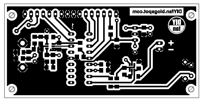
Schematic


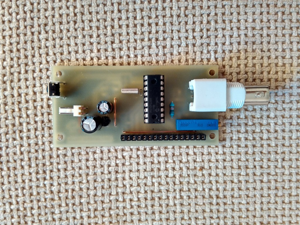
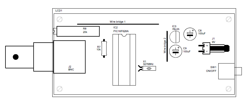
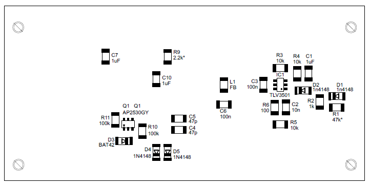
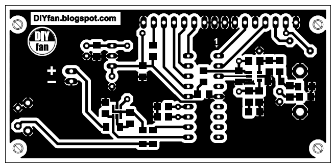


tres interessant,à guarder et realiser des que possible
which it is the value of L1 FB
This is a simple ferrite bead for limiting the noise injected to power net. If you don’t have a ferrite bead use a simple wire.
The power wire pull across a ferrite ring.
Hello I want to make this, but have a problem!
I can’t find AP2530GY mosfet available. Market says it is not available anymore. Should I change the model and edit the PCB work?
Also, is there any trade offs between this version and https://www.electronics-lab.com/project/100mhz-frequency-counter-with-pic16f628a/ (LED) version?
LED version seems easier to make, and have same frequency resolution. If the spec is similar, I am thinking to work on LED version.
Thank you.
Hi,
Can you tell me what C compiler was used for the C code as I need to make some small alterations.
thanks
The article says “MikroC” and I believe it.
please help.i cannot program the chip. i keep getting a error.
Hello, I am also going on this project and are in troubles.
Which errors are you getting? I am currently using MPLAB X IDE v.345 with xc8(v1.38)
I am getting errors such like (Unexpected tokens at sbit assignation).
Could we help each other?
I’m using pickit2 programmer.i also have a minipro programmer and I get errors while programming.
I finally managed to make some small alterations to the program using mikroC pro for PIC which is easier to use than MPLAB. I didnt get any compile errors using the given C program and I even got the hex code to program on a chinese K150 programmer! The hex code of original and modified versions works fine. Hope this helps.
Can you send me the hex file at domdomgin@yahoo.com.
Please.
The .hex file is on the rar file “FreqCounter_Source_Code.rar” above.
when i load the hex file i get a error before the programming ends.
Can i do anything.
What error did you get?
Hello,
I need to add some features in the existing code. Can you please share the complete code (along with the LCD driver). Currently I see only the main c file which can’t be compiled without the LCD driver. I already have made the PCB and waiting for updating the code.
Thanks a lot.
Error: With Chinese “K150 v150807″; the message: ” Fuse Error 0x2007 Good 0x2158 Bad 0x3F58 “
?
MikroC Pro provides built in libraries for interfacing LCDs with HD44780 compliant controllers, so you don’t need an external library.
Hi,
Thanks for your reply.
Can you please clarify if you are using the INTERNAL OSCILLATOR (4MHz) of PIC and what purpose you are using 32kHz oscillator for?
Moreover, what config settings we need to set in the MikroC especially for the oscillator.
Thanks
One more question,
I am using this http://eu.mouser.com/Search/ProductDetail.aspx?R=NHD-0216K1Z-FL-YBWvirtualkey66010000virtualkey763-0216K1Z-FL-YBW LCD, how to confirm if it uses HD44780 compliant controller.
Thanks
Most of these displays uses a HD44780 compatible controller, but i can’t either confirm that from the datasheet.
Hi,
I am able to compile using MikroC. I am programming the chip using PICkit3 using 5 pin header and MPLAB IPE. The problem is that, the chip gets programmed well for the first time but gives communication error and does not get programmed in later attempts.
This problem does not happen when I program any other code (like LED blinking) over and over again.
So I felt as if there is some kinda code protection enabled which does not allow me to program for the second time.
But I have also checked the config bits, the code/data/flash protection is OFF.
Can you please help me in identifying the problem?
Hi,
I am able to fix the issues and can reprogram the chip as many times as I want. This topic helped me figuring out the problem
http://www.microchip.com/forums/tm.aspx?m=303686&mpage=2&key=񋕲
Now, the circuit is working and counting frequency TILL 87MHz ONLY as soon as I give 88MHz to its input, the measured value drops and starts giving wrong frequency.
Can you suggest why I am into this limit while you were able to measure till 200MHz? Actually my frequency range of interest is 100MHz to 200MHz.
I have made some changes in my circuit compared to yours, these changes are as follows:
1. No ON/OFF switch and its corresponding circuitry, directly feeding the power through 7805 chip with caps
2. Using SMD version of all components including PIC, caps and xtal etc. No through hole so my PCB is single sided only
3. Not using 4148 Diodes (keeping input amplitude = 300mV)
4. Using R1=50 ohm instead of 47k as my oscillating circuit has O/P impedance of 50 ohm
5. Using 12pF caps instead of 47pF (I just noticed it but I can replace them)
What do you think, can anyone of above changes cause any trouble in frequency range?
Thanks
EDIT: Clarification of comment 5
I am using 12pF cap with crystal because this is what is suggested by the XTAL datasheet.
Regarding frequencies over 80Mhz I am suspicious that only some pics will respond. I intend to use an external prescaler divide by 10 which works to more than 1Ghz. I chose MC12080(ebay). In this case little or no modification will be required to the code since you can figure out the reading easily. this prescaler only needs a few capacitors and one resistor to work. A small circuit diagram is available if you need it.
Regarding the power off circuitry I have not included it as the whole thing works from a small 5v power adapter.
“So the maximum frequency can be between 100Mhz and 256MHz.” That statement seems incorrect, but hey, I don’t know much about the PICs. So who am i to argue.
Dear Terry,
Thanks for your response. I have looked into datasheet of MC12080, as it uses D flip flop to divide the frequency, so it should work on square wave, right? but the datasheet also shows the input signal source as sinusoidal, can you please clarify if I can use this chip fed directly with sinusoidal signal?
If this is the case, then I may use the comparator at the output of MC12080 (Divided by 10) before feeding to controller.
Right?
Your suggested will highly be appreciated.
Thanks
Muhammad,
I cant answer your question about sine and square wave with the MC12080 as I have ordered two but they have not arrived yet. However from experiments I have conducted I find that the input circuitry design of a frequency counter is very critical so that if there is any noise or whatever on the input it shows up as unstable readings. Square waves are sometimes problematic as the edges are not always clean. The input needs a good filter for the frequency range you are interested in and control over the upper and lower limits as per comparator IC or schmidt trigger and that TLV3501 may need some feedback. Anyway thats what experimentation is about so good luck with your project.
Hello ,
Im relative new to electronics and im trying to understand the schematic, but what purpose does the capacitor c1 serve? is it for filtering or something else?
Hello and welcome! C1 is used to block any DC voltage that may appear on the input signal and allow only AC to pass.
Ah i see. I have another question is iτ possible to swap the PIC16F628A for an arduino? if so do i need some kind of prescaler circuit before the input of the arduino?
You may use Arduino instead of PIC but the source code must be re-written.
Hello, what are config registers for the source file? I can’t find them there. Tank you.
Hello,
there’s a problem with a hex file. Tried to program PIC via ql-200 programmer and with Pickit3. At the end programmer throws error.
After that, PIC is no longer programmable (broken).
Could you please describe programming steps and what programmer do you use?
For anyone with this problem:
first of all you need to slightly change code:
add
delay_ms(2000);
Below
CMCON = 0b00000111; (line 76’sh)
Purpose of this is to wait before configuring TMR0. If TMR is enabled too soon, – programmer will not be able to push firmware into PIC.
This changes allowed me to program PIC using Pickit3.
Config bits:
INTOSC: I/O
WDT: off
Power-up timer: off
RA5/MCRL: off
Brown-out: off
Low voltage programming: off
Memory code protection: off
Flash protection: off
This also fixes issue where you cannot reprogram PIC
.
DS8629 divide by 100 prescalar.
dc -120MHZ (600mv sine)
single or differential input
TTL input
TTL output
available on E-bay under $10
(Probably a chinese knock-off of the original National Semiconductor part)
Hi friend, interested project great work. I am working on frequency counter, i need your help. I need to develop code for arduino uno or any other avr microcontroller. i have to measure 1 Hz to 100 Mhz square wave signal with 16 x 2 lcd.
This dude has counters for Arduino, he is saying that you can count up to 6 MHz only. http://mfprojects.co.uk/lcd_counter.php
It really would be wonderful if you would upload your code to github. This would solve many problems with fixing some issues with the code.
Two problems with that TLV3501 comparator: the max guaranteed toggle rate is 80MHz, and at low speeds (below ~50KHz) you may have unavoidable chatter on the output as noise on input or power is interpreted as an edge, especially so on a single-layer board like this. The default hysteresis for that part is only 6mv, so you might want to review the section on the datasheet titled ‘Adding external hysteresis’. You might also want to consider swapping that comparator out for an ECL prescaler like the MC12080, with a transistor output buffer to get the output up to a decent logic level.
I don’t want to be offending, but am afrid, the high limit of your frequency counter is way overestimated.
A short blink on the datasheet reveals that the shortest pulse width of the input signal, for Timer0 counter in the PIC16F628A, is 10 ns. A period contains two pulses, one positive and one negative, so the highest specified frequency is 50 MHz. A practical value can be higher than that, but 100 MHz is very unlikely, let alone the 200 plus MHz. You state more than one PIC628A-based counter you built was able to measure frequencies beyond 200 MHz. Hard to believe that. This would mean around 2.3 ns input pulse width…
I can see the proof on an oscilloscope screen. I am curious to know, what IC on the breadboard produces the more than 215 MHz test signal. That must be an ECL device, or perhaps one off the 74G series, however, achieving 200 plus MHz with such build technology leaves questions.
In one of the comments Mr. Karimi observed the highest frequency limit being 87 MHz, that seems fully reasonable.
Could you ease my doubts and anxiety, please? Thanks in advance,
Laszlo
Which version of EAGLE program should I use, since my version of EAGLE 6.0 will not open the PCB file? Thank you.
I made this frequency counter and tested it. The input fed the frequency from the si5351 and he measured the frequency up to 250MHz. If you apply more frequency, the changes become incorrect. What the maximum frequency is limited by: firmware pic16f628a, tlv3501 maximum or pic16 TMR0 maximum.
The maximum output frequency of the SI5351 is 133MHz, according to its datasheet. How did you achieve 250 MHz?
This can be achieved by overclocking the SI5351, which is not recommended for sensitive circuits.
prescaler = 256; // sets the initial value of prescaler
prescaler_bits = 0b00000111; // sets the initial value of prescaler bits
// calculating prescaler
// f1 holds the input frequency divided by 256*128 and multiplied by time period 0.08191s
// if the frequency is above 102.4MHz prescaler = 256
// 102.4MHz .. 51.2MHz -> prescaler = 128
// 51.2MHz .. 25.6MHz -> prescaler = 64
// 25.6MHz .. 12.8MHz -> prescaler = 32
// 12.8Mhz .. 6.4MHz -> prescaler = 16
// 6.4MHz .. 3.2MHz -> prescaler = 8
// 3.2MHz .. 1.6Mhz -> prescaler = 4
// 1.6MHz .. 800kHz -> prescaler = 2
// 800khz .. 0 -> prescaler = 1
f1 <<= 1;
while (f1 < prescaler) {
prescaler >>= 1; // divide prescaler by 2
prescaler_bits–;
}
if (prescaler < 2) {
prescaler = 1;
OPTION_REG = 0b00101000; // TMR0 prescale 1:1
prescaler_bits = 0;
}
else {
OPTION_REG = 0b00100000 | prescaler_bits; // TMR0 prescale
prescaler_bits++;
please help me to know why you did this and how to did the calculation.
My si5351a module ordered from aliexpress stably generated frequencies up to 310 MHz. I controlled the si5351 library with the help of arduino, corrected since the adafruit library did not allow dividing the frequency by 4. I took the corrected si5351a library from the github, you need to search. Also on this frequency meter, I reassigned the ra6 and ra7 pins and connected a 20 MHz quartz to these pins and launched the microcontroller on this quartz. Now the maximum frequency that I could measure stably is 268 MHz. At frequencies of 272~275MHz, the frequencies jump by 1~2MHz.
Hi everyone
Someone compiled this in proteus?
Please help me
Hi,
my programmer needs to know fuses settings:
0) FOSC 0
1) FOSC 1
2) WDTE
3) PWRTE
4) FOSC 2
5) MCLRE
6) BODEN
7) LVP
8) CPD
9) —
10)–
11)–
12)–
13)CP
Any help appreciated!
Paul
Hi,
if someone is interested: the right ( at least for me ) setting for config fuses is:
CPD LVP MCLRE WDTE FOSC1 FOSC0
…and it work perfectly!
Paolo
Can you please clarify? These are ON and rest are OFF ?
Hi,
can you help me with fuses config?
My programmer ( mini pro programmer) needs to know:
FOSC0
FOSC1
WDTE
/PWRTE
FOSC2
MCLRE
BODEN
/LVP
/CPD
/CP
Thank you!
Paul
Hi,
some PIC16F628 can be programmed without problems, others say : wrong fuse config:
( of course always with this freq counter-same fuses config) why?
This is happening with some pic628 I’ve used before, but they all are OK if I program other file.hex inside them.
My programmer can only program PIC16f628A : what the differencies from 16F628?
I’m confused: some help needed…….
Paul