USB PIC Programmer
- Stefano Purchiaroni
- http://www.purchiaroni.com
- 93.629 Views
- medium
- Non tested
This page is dedicated to everybody needs to program a PIC (Microchip) device via USB port. Looking on the web for ready-to-use projects, I found a good one called Open Programmer, coming with several schematics, PCBs and Open Source code. The original link is http://openprog.altervista.org/OP_ita.html
What concerned me was the need to mount, on the mainboard, a specific socket board depending on the model of PIC being programmed. Moreover, the proposed layout did not meet my personal “compact look” ideas. So, I propose here a small layout version of that circuit, adopting a single smart on-board ZIF socket. This version sacrifices many non-PIC microcontroller models. I will thank everybody proposing a larger range implementation, suitable to program Atmel and other devices. Anyway, if your goal is to program PIC devices, you are on the good site.
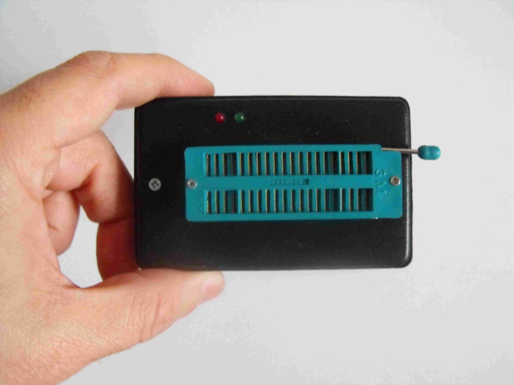
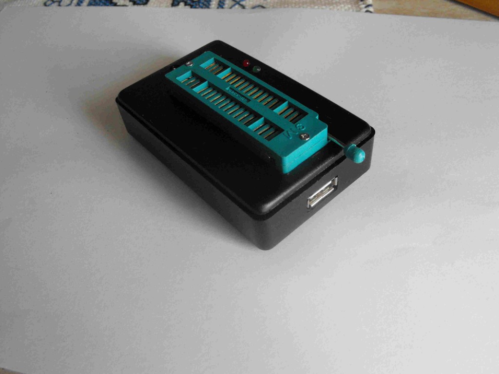
A small box, a USB connector, a ZIF socket, two leds. That’all in my compact proposal.
Description
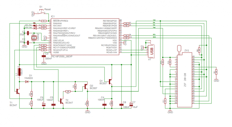
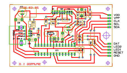
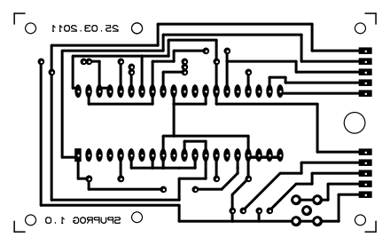
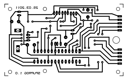
The details are available on the original project mentionned above. Hereafter, I shown my Compact version, with a schematic, PCB layout and instruction for assemby and inserting it in a very common little plastic box. At the bottom of this page, I supply a copy of the program to load on the PIC18F2550 used to manage the programming functions, as well as a copy of the PC side program. I tested the program up to Win-8 without problems. Take into account that, on the original site, a newer version of both Firmware and Software is available.
Schematic
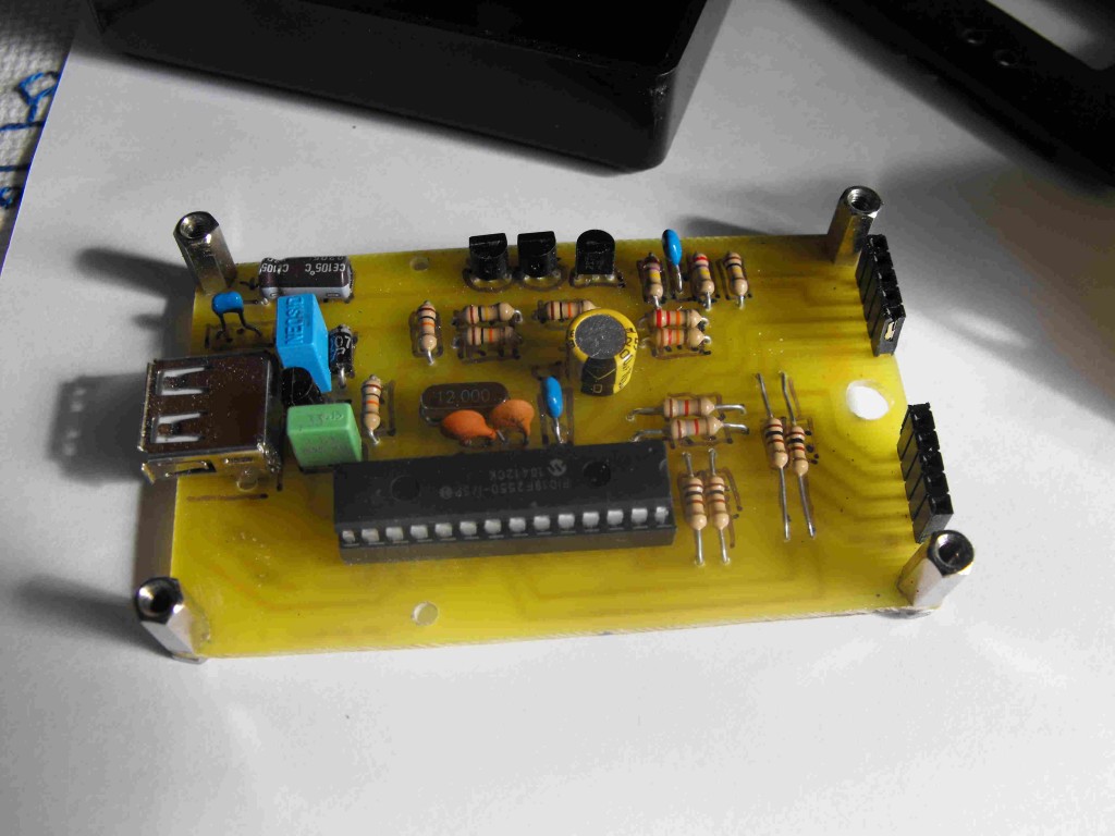
Assembly
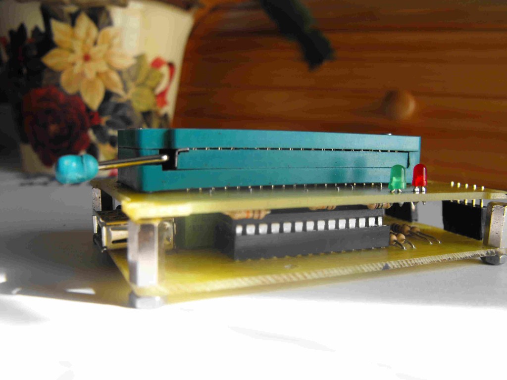
Build first the main module using low profile components being under 10 mm of height from the PCB surface, since a second board will be mounted over that one. Mount 4 ten millimeters height columns to allow the final assembly of the second board. Use low profiles parts to fix the columns, otherwise some manual metals removal can be needed to reduce the occupation on the copper side.
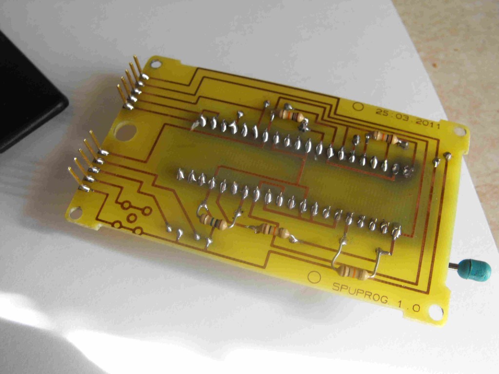
The ZIF is a quite delicate component befor final soldering. Pay attention to avoid any force that can lead to damage or deformation. It is better to do 1.2 mm holes to facilitate the insertion of the ZIF socket in the PCB. During soldering jump several pins each time, following a spiral line, adopting a sequence that allow to warm-down a pin while you are soldering the next one.
Once the two circuits are ready, connect them using the strip lines, and block assembly using the columns. Use countersunk screws of countersunk holes to avoid the screws being too hight respect to upper surface of second PCB. Just the socket and the two leds shall emerge.
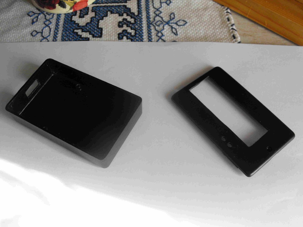
The plastic box is very common. You shall create holes to let emergent parts to exit from its surface: the socket, the two leds (or a single bi-colour led), the USB socket on a short side. It is a A-type female
The Box
After a few attempts and corrections you will reach the final result. The cover has a border that shall be modified to host the circuits, but your logic will drive you. The first PCB has to be fixed on the box using the supplied screws.
Hereafter the final result:
Software
As said before, the original site offers both the firmware and the PC side software. Anyway, to start using this programmer, I suggest you to use the versions I used at time of project editing, available hereafter for downloading. After some tests, you can try the new updated versions available on the original site. Of course, if you have not a programmer yet, a friend should program the programmer first, for you. After that first step, you will be automous!
You can download the PC software on the link below – OpenProg.rar
You can download the PIC .hex file on the link below – OProg.hex
Usage
Connect the programmer to the PC with a male-male A-Type USB cable. The device is seen as a generic one. The green led blinks speedy first, announcing the connection in progress. Than slowly, indicating that the connection phase is completed. The PC software allows bot writing and reading the EEPROM of any PIC mounted on the ZIF socked. The test functions allow to measure the Vpp high voltage generated by the step-up converter present on the main circuit. That voltage is anyway already verified by the firware itself.
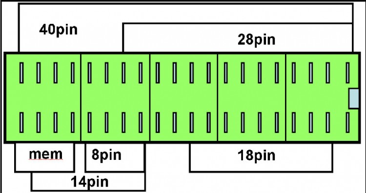
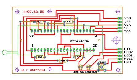
The PIC to be programmed has to be positionned on the ZIF socket as shown by the following picture. An hi-res version of this picture is available HERE for being printed and attached on the back of the programmer itself.




Does it work on windows 10 or 11 ?
The software is located here: https://sourceforge.net/projects/openprogrammer/ and I would suggest trying to run it on your OS. Please let us know the results here.
Why did you put Vpp on pin 5? Won’t it damage the chip? Maybe I fried my 25K50 that way.