Brushed DC Motor Speed Controller Using Radio Control (RC) Remote
- Rajkumar Sharma
- 533 Views
- medium
- Tested
- SKU: EL136367
- Quote Now
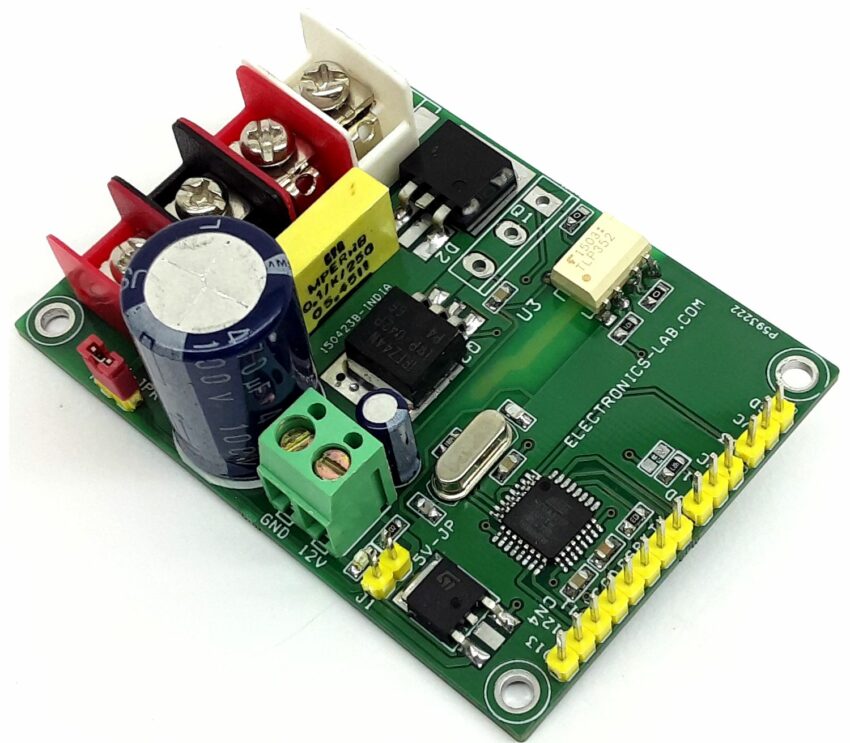
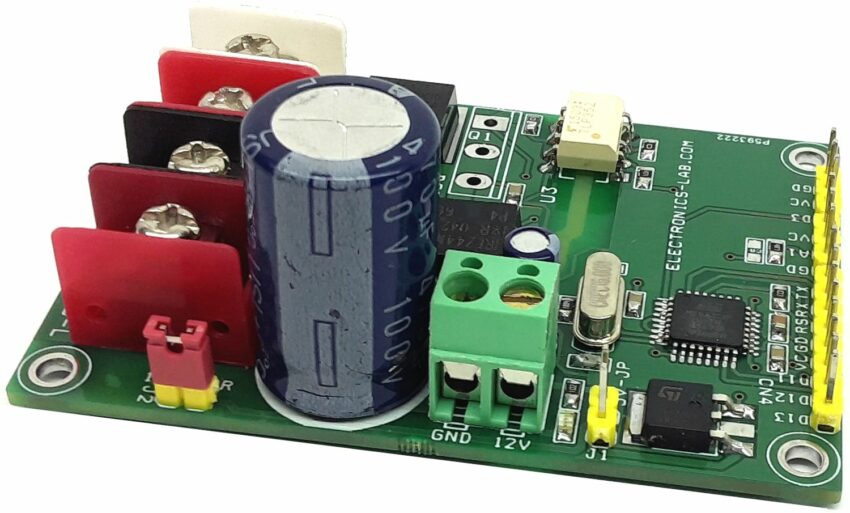
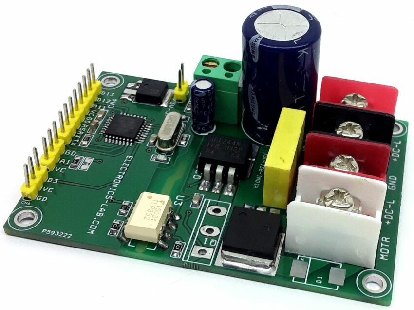
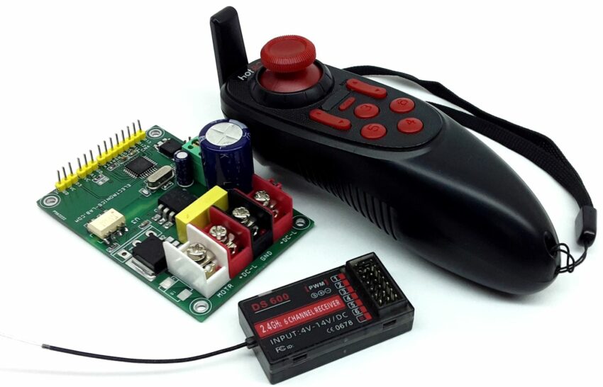
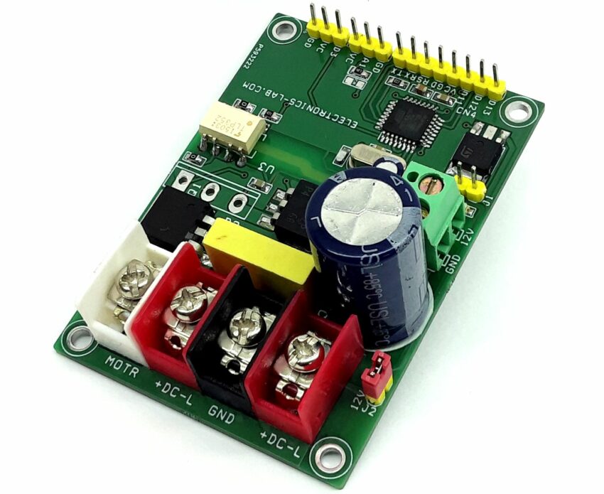
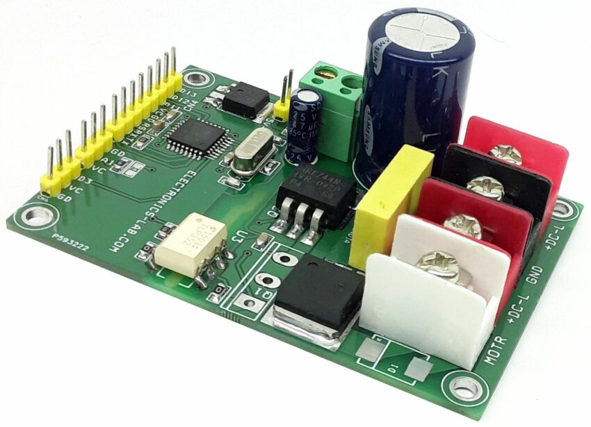
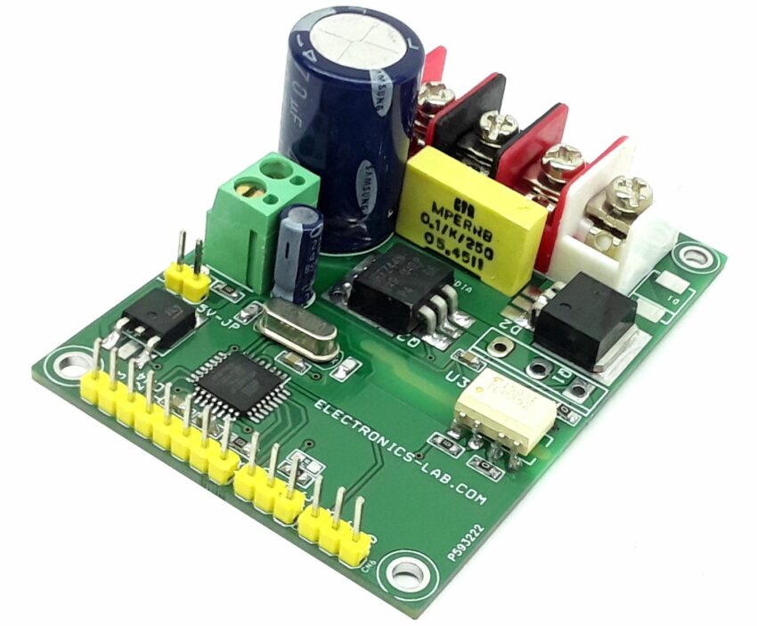
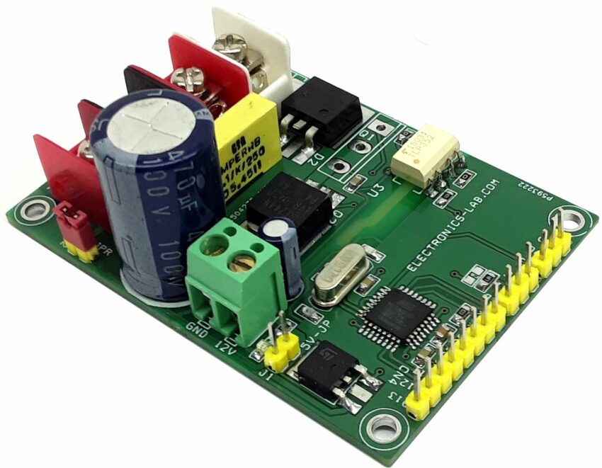
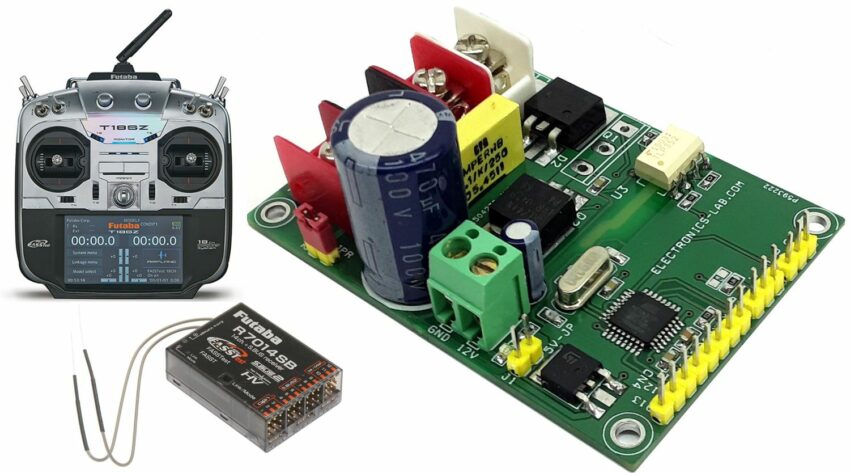
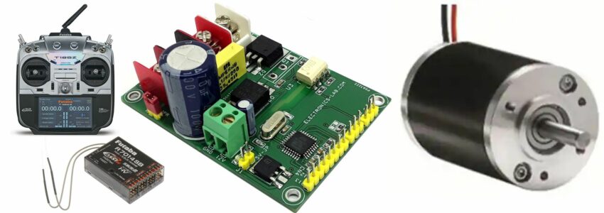
This is a Brushed DC motor controller designed to control one brushed DC motor up to 5A. It can control the speed of the DC motor using a Radio Control (RC) System. This Arduino compatible hardware converts RC PWM signal into 0 to 100% duty cycle PWM which further drives high current load using MOSFET. The project consists of an Atmega328 microcontroller, and a gate driver optocoupler provides isolation between MOSFET and microcontroller circuit to prevent high voltage and noise traveling from the motor and related circuit to the microcontroller. The circuit can drive a motor up to 5A with a power supply of 12V to 40V DC. The board has the option to mount higher voltage and current MOSFET, which can drive higher Voltage and current load. In this case don’t install Q2, install Q1 MOSFET FDH3632, and replace diode D2 with a higher current diode.
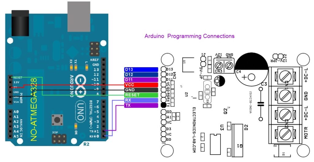
Arduino Programming
Arduino code is available as a download below and the user will able to test the board using this code. Feel free to modify the code as per requirement.
More info for programming a new Atmega328 chip: https://docs.arduino.cc/built-in-examples/arduino-isp/ArduinoToBreadboard
Power Supply
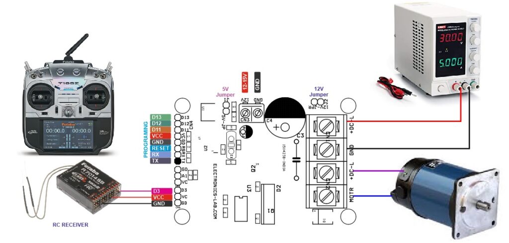
- For Motor up to 12-15V the board can work with a single supply. Close jumper J1 and Jumper J2, and use connector CN1 to apply 12V to 15V DC.
- For Higher Voltage up to 90V (Limited due to DC bus capacitor), the board requires dual supply, one for DC motor load, 2nd for gate driver 12V to 15V on CN3.
- It is advisable to use 3 separate power supplies for large-size motors such as 90V, 20A. such as 1. Logic supply 5V. 2. Gate Driver Supply 12V to 15V and Load supply 90V DC.
- Use Connector CN1 for load power supply up to 90V DC, Gate driver requires 12V to 15V power at CN3, and use CN5 Pin 1-5V DC and Pin 3 GND to power the microcontroller.
Features
- Power Supply up to 40V (Read description for higher power input)
- Load Current Up to 5Amps
- Dual Supply 12V-15V DC for Gate driver and 40V for the Load
- On Board Power LED
- Optocoupler MOSFET Gate driver for noise immunity and provides isolation between micro-controller and MOSFET
- Arduino Compatible Hardware to create many applications
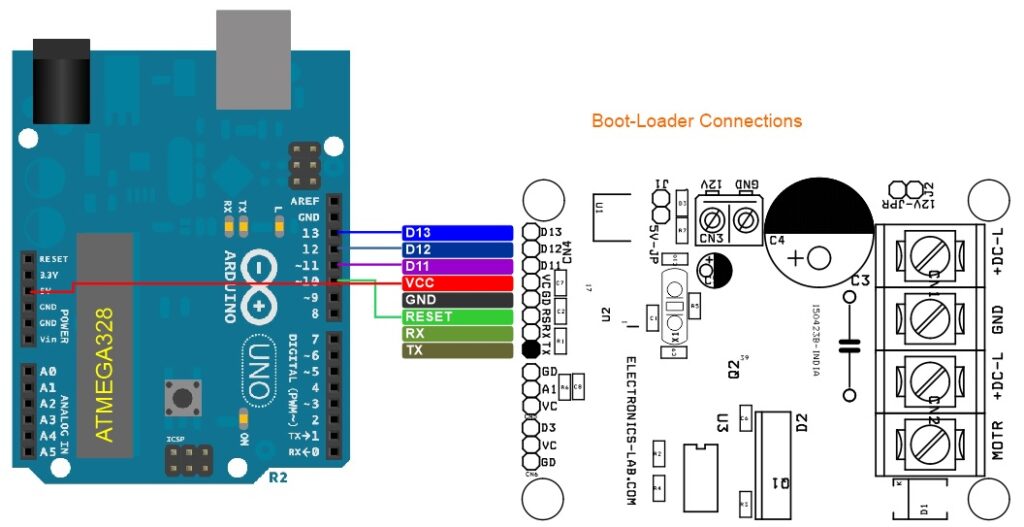
- On Board Connector for Arduino Programming and Boot-Loader burring
- Barrier Terminal Blocks for easy connection of Motor and power supply
- Onboard 5V Regulator for single supply operation for lower voltage motor
- PCB Dimensions 74.45 x 52.23 mm
- 4 x 3mm Mounting Holes
Connections and Other Details
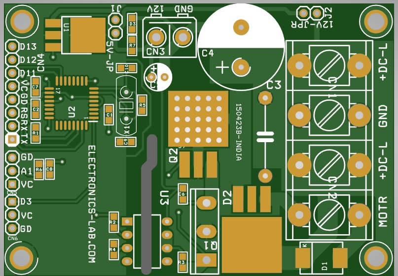
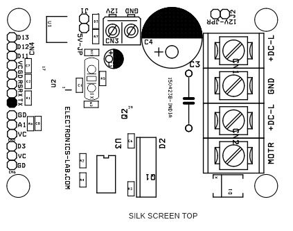
- CN1: Pin 1 = + DC Supply for Load, Pin 2 = GND
- CN2: DC Brushed Motor, Pin 1 = Motor, Pin 2= Motor
- CN3: Gate Driver Power Supply 12V to 15V, Pin 1 = +12V to 15V, Pin 2 = GND
- CN4: Programming and Boot-Loader, Pin 1 = TX, Pin 2 = RX, Pin 3 = Reset, Pin 4 = GND, Pin 5 = VCC, Pin 6 = D11, Pin 7 = D12, Pin 8 = D13
- CN6: RC Receiver, Pin 1 = D3 – RC PWM Input, Pin 2 = VCC 5V, Pin 3 = GND
- J1: For lower voltage single supply option, Close Jumper 1, Jumper J2, Use CN1 to power 12V to 15V DC.
- J2: For Lower Voltage motor 12V to 15V Close Jumper J2 to power the Gate driver
- For Higher Voltage motor such 90V, advisable to use three power supply, Load Supply CN1, Gate driver Supply 12V to 15V CN3, Logic supply 5V CN5, open jumper J1 and J2 in this case
- CN5: Do not Install
- D3: Power LED
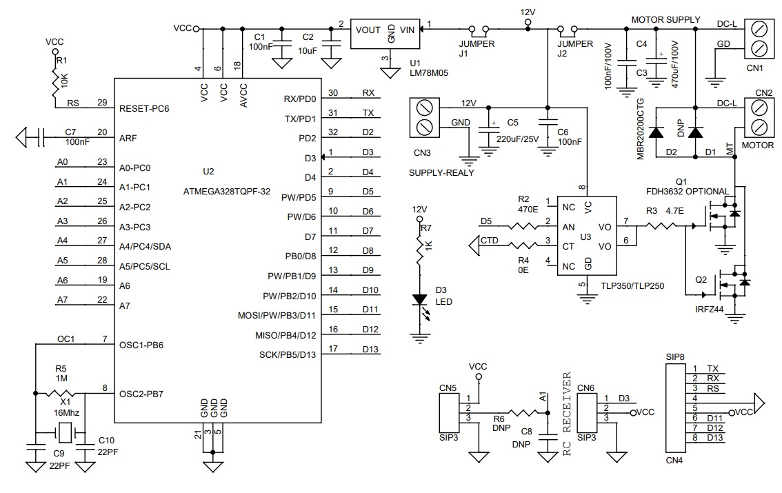
Schematic
Parts List
| NO | QNTY | REF. | DESC. | MANUFACTURER | SUPPLIER | SUPPLIER'S PART N0 |
|---|---|---|---|---|---|---|
| 1 | 1 | CN1 | 2 PIN BARRIER CONNECTOR PITCH 9.53MM | TE CONNECTIVITY | DIGIKEY | A98482-ND |
| 2 | 1 | CN2 | 2 PIN BARRIER CONNECTOR PITCH 9.53MM | TE CONNECTIVITY | DIGIKEY | A98482-ND |
| 3 | 1 | CN3 | 2 PIN SCREW TERMINAL PITCH 5.08MM | PHOENIX | DIGIKEY | 277-1247-ND |
| 4 | 1 | CN4 | 8 PIN MALE HEADER PITCH 2.54MM | WURTH | DIGIKEY | 732-5321-ND |
| 5 | 2 | CN5,CN6 | 3 PIN MALE HEADER PITCH 2.54MM | WURTH | DIGIKEY | 732-5316-ND |
| 6 | 3 | C1,C6,C7 | 100nF/50V CERAMIC SMD SIZE 0805 | YAGEO/MURATA | DIGIKEY | |
| 7 | 1 | C2 | 10uF/16V CERAMIC SMD SIZE 0805 | YAGEO/MURATA | DIGIKEY | |
| 8 | 1 | C3 | 100nF/100V THT FILM | CORNELL | DIGIKEY | 160104K160C-F-ND |
| 9 | 1 | C4 | 470uF/100V ELECTROLYTIC | NICHICON | DIGIKEY | 493-1379-ND |
| 10 | 1 | C5 | 220uF/25V ELECTROLYTIC | RUBYCON | DIGIKEY | 1189-2913-ND |
| 11 | 2 | SHUNT | SHUNT FOR JUMPER J1 AND J2 | SULINS CONNCT | DIGIKEY | S9001-ND |
| 12 | 3 | D1,R6,C8 | DNP | |||
| 13 | 2 | C9,C10 | 22PF/50V CERAMIC SMD SIZE 0805 | YAGEO/MURATA | DIGIKEY | |
| 14 | 1 | D2 | MBR20200CTG TO263 | ONSEMI | DIGIKEY | MBR20200CTGOS-ND |
| 15 | 1 | D3 | LED RED SMD SIZE 0805 | OSRAM | DIGIKEY | 475-1278-1-ND |
| 16 | 2 | J1,J2 | JUMPER 2PIN MALE HEADER PITCH 2.54MM | WURTH | DIGIKEY | 732-5315-ND |
| 17 | 1 | Q1 | FDH3632 OPTIONAL TO247 | ON SEMI | DIGIKEY | DO NOT INSTALL |
| 18 | 1 | Q2 | IRFZ44 | INFINEO | DIGIKEY | IRFZ44NSTRLPBFTR-ND |
| 19 | 1 | R1 | 10K 5% smd size 0805 | YAGEO/MURATA | DIGIKEY | |
| 20 | 1 | R2 | 470E 5% smd size 0805 | YAGEO/MURATA | DIGIKEY | |
| 21 | 1 | R3 | 4.7E 5% SMD SIZE 0805 | YAGEO/MURATA | DIGIKEY | |
| 22 | 1 | R4 | 0E SMD SIZE 0805 | YAGEO/MURATA | DIGIKEY | |
| 23 | 1 | R5 | 1M 5% SMD SIZE 0805 | YAGEO/MURATA | DIGIKEY | |
| 24 | 1 | R7 | 1K 5% SMD SIZE 0805 | YAGEO/MURATA | DIGIKEY | |
| 25 | 1 | U1 | LM78M05 SMD DPAK | TI | DIGIKEY | MC78M05CDTGOS-ND |
| 26 | 1 | U2 | ATMEGA328TQPF-32 | MICROCHIP | DIGIKEY | ATMEGA328PB-AURCT-ND |
| 27 | 1 | U3 | TLP350/TLP250 | TOSHIBA | DIGIKEY | TLP350F-ND |
| 28 | 1 | X1 | 16Mhz | ECS INC | DIGIKEY | X1103-ND |
Connections
Gerber View
Photos
Video


