

DC Motor Position Control Using Potentiometer – Arduino Compatible
- Rajkumar Sharma
- 875 Views
- medium
- Tested
- SKU: EL138890
- Quote Now
- 0 Likes

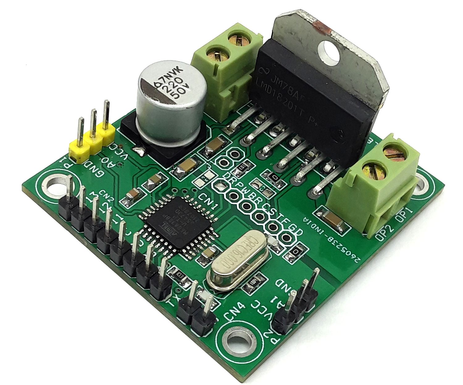
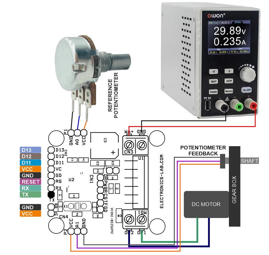
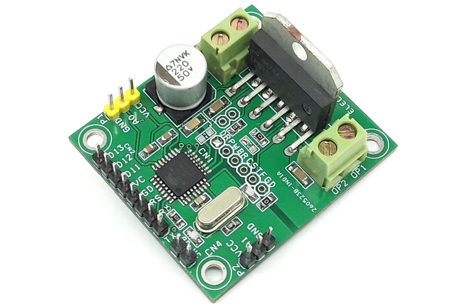
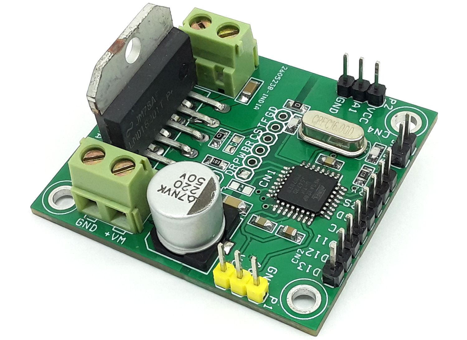
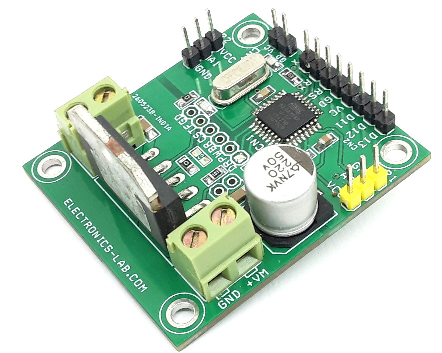
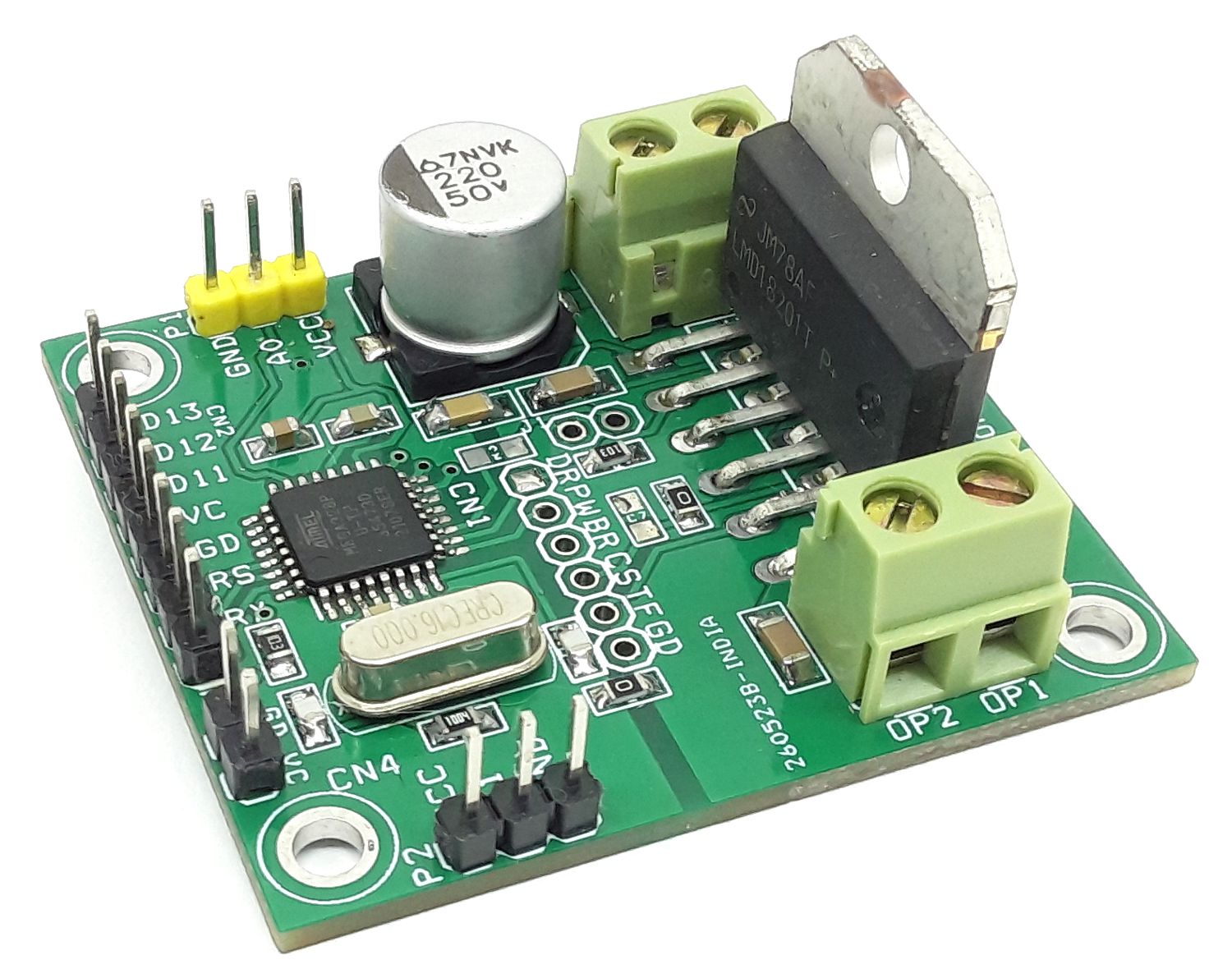
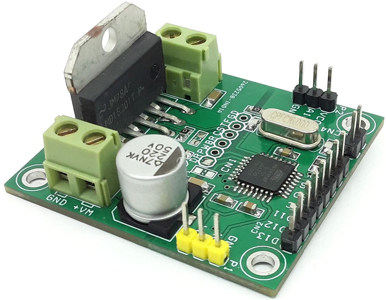
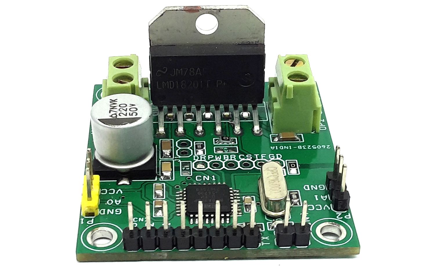
The project presented here is an Arduino-compatible motor control board. The board consists of an ATMEGA328 microcontroller, LMD18201 H-Bridge, and 2 x potentiometers. This closed-loop servo system provides position control using a feedback potentiometer mounted on the output shaft of the gearbox and provides position control by turning the shaft of the reference potentiometer, the motor-gearbox output shaft follows the reference potentiometer. The project can also be used in other applications that require Arduino-compatible hardware and H-Bridge.
The project requires a special mechanism, where the DC motor’s output shaft is mechanically coupled with the potentiometer shaft using a reduction gear. Approx. reduction ratio 15-50: 1. When the reference pot is turned, the motor shaft follows the position. This will provide a maximum rotation of 270 degrees. Multi-rotation is possible with the help of a multiturn potentiometer.
Arduino Code
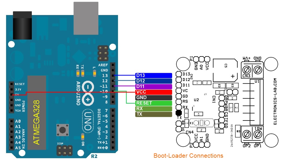
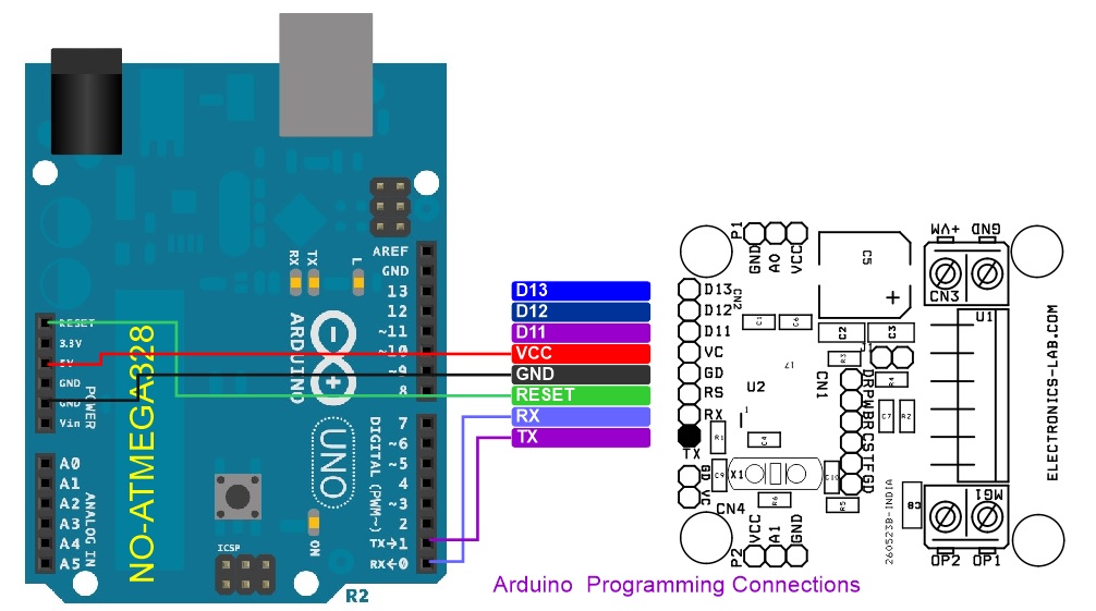
Arduino example code is available and the board can be programmed using the CN2 connector, the same connector helps burn the boot-loader to a new ATMEGA328 chip.
Refer to the following link for more info about Arduino programming: https://docs.arduino.cc/built-in-examples/arduino-isp/ArduinoToBreadboard
This is a modified code, original author of the code: http://geekeeceebee.com
Note: It is important to tune the PID values in Arduino code to set your DC motor for smooth operations.
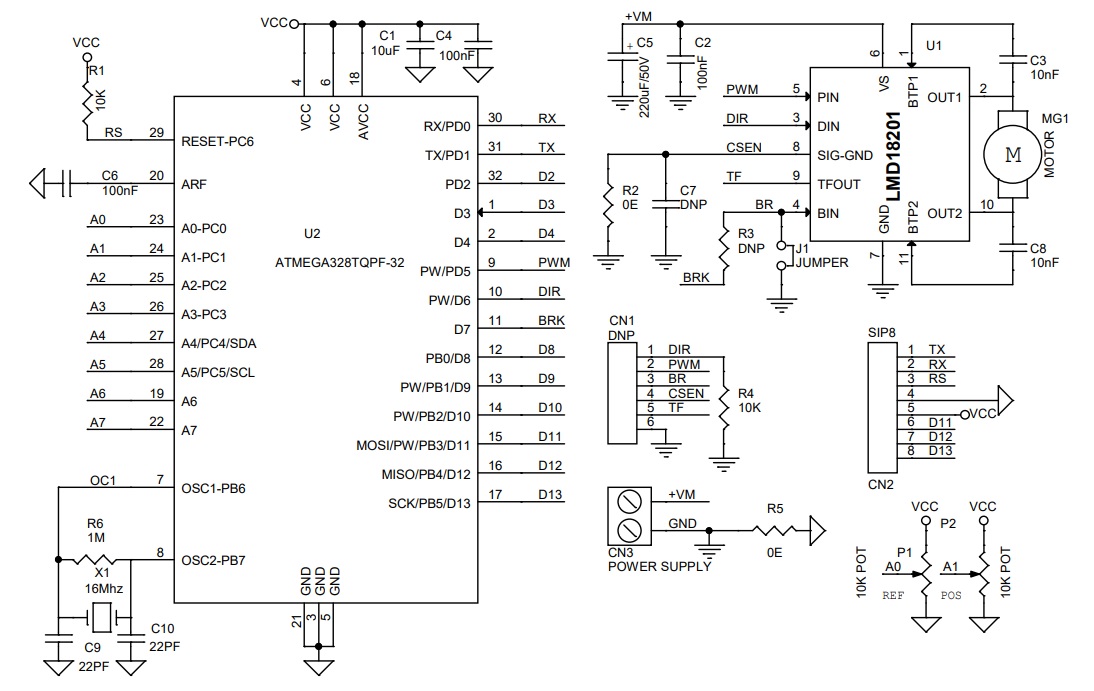
Arduino Pins vs H-Bridge LMD18201
- Arduino D5 = PWM
- Arduino D6 = Direction
- Arduino D8 = Brake (Not Used -Optional)
- Arduino A0 Reference Potentiometer, A1 Feedback Potentiometer
Features
- Power Supply Motor 12V to 40V (48V Max)
- Motor Load 3A (Peak 6A)
- Logic Supply 5V DC @ 20mA
- On Board Jumper J1 for Brake, Closed for Normal Operations
- On Board Programming Connector for Arduino IDE
- Screw Terminals for Motor and Power Supply
- 2 X 3 Pin Male Header for Feedback and Reference Potentiometers
- Arduino Compatible
- PCB Dimensions 47.63 x 42.55mm
- 4 x 3MM Mounting Holes
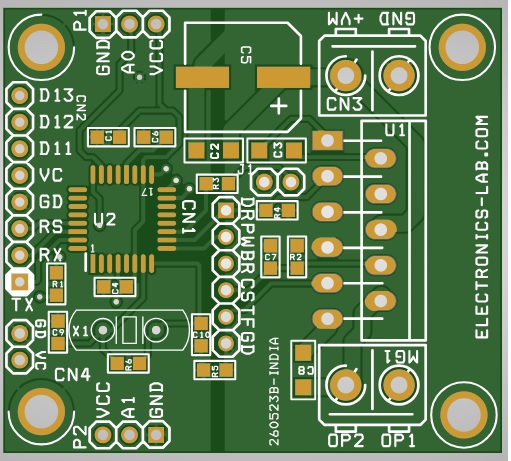
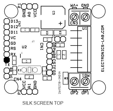
Connection & Other Details
- CN1: Optional Do Not Install
- CN2: Programming Connector Pin 1 = Tx, Pin 2 = Rx, Pin 3 = Reset, Pin 4 = GND, Pin 5 = VCC, Pin 6 = D11, Pin 7 = D12, Pin 8 = D13
- CN3: Pin 1 = Motor Power Supply, Pin 2 = GND
- MG1: Pin 1 = Motor 1, Pin 2 = Motor 2
- P1: Reference Potentiometer
- P2: Feedback Potentiometer
- J1: the jumper must be closed to enable the Brake for normal operation.
Schematic
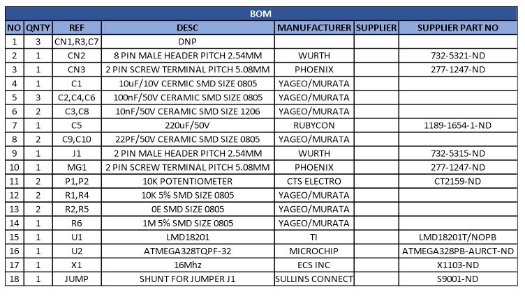
Parts List
| NO | QNTY | REF | DESC | MANUFACTURER | SUPPLIER | SUPPLIER PART NO |
|---|---|---|---|---|---|---|
| 1 | 3 | CN1,R3,C7 | DNP | |||
| 2 | 1 | CN2 | 8 PIN MALE HEADER PITCH 2.54MM | WURTH | 732-5321-ND | |
| 3 | 1 | CN3 | 2 PIN SCREW TERMINAL PITCH 5.08MM | PHOENIX | 277-1247-ND | |
| 4 | 1 | C1 | 10uF/10V CERMIC SMD SIZE 0805 | YAGEO/MURATA | ||
| 5 | 3 | C2,C4,C6 | 100nF/50V CERAMIC SMD SIZE 0805 | YAGEO/MURATA | ||
| 6 | 2 | C3,C8 | 10nF/50V CERAMIC SMD SIZE 1206 | YAGEO/MURATA | ||
| 7 | 1 | C5 | 220uF/50V | RUBYCON | 1189-1654-1-ND | |
| 8 | 2 | C9,C10 | 22PF/50V CERAMIC SMD SIZE 0805 | YAGEO/MURATA | ||
| 9 | 1 | J1 | 2 PIN MALE HEADER PITCH 2.54MM | WURTH | 732-5315-ND | |
| 10 | 1 | MG1 | 2 PIN SCREW TERMINAL PITCH 5.08MM | PHOENIX | 277-1247-ND | |
| 11 | 2 | P1,P2 | 10K POTENTIOMETER | CTS ELECTRO | CT2159-ND | |
| 12 | 2 | R1,R4 | 10K 5% SMD SIZE 0805 | YAGEO/MURATA | ||
| 13 | 2 | R2,R5 | 0E SMD SIZE 0805 | YAGEO/MURATA | ||
| 14 | 1 | R6 | 1M 5% SMD SIZE 0805 | YAGEO/MURATA | ||
| 15 | 1 | U1 | LMD18201 | TI | LMD18201T/NOPB | |
| 16 | 1 | U2 | ATMEGA328TQPF-32 | MICROCHIP | ATMEGA328PB-AURCT-ND | |
| 17 | 1 | X1 | 16Mhz | ECS INC | X1103-ND | |
| 18 | 1 | JUMP | SHUNT FOR JUMPER J1 | SULLINS CONNECT | S9001-ND |
Connections
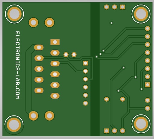
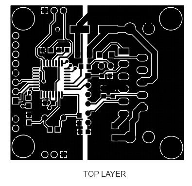
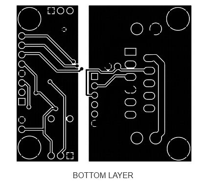
Gerber View
Code
//GeeKee CeeBee
// ************ DEFINITIONS************

int potPin = A0;          // Reference Potentiometer
int encoder_pot = A1;    // Position Feedback sensor

int val = 0;
int encoder_val =0;
float kp = 0.2;
float ki = 0.00000 ;
float kd = 2.00;
float Theta, Theta_d;
int dt;
unsigned long t;
unsigned long t_prev = 0;
int val_prev =0;
float e, e_prev = 0, inte, inte_prev = 0;
float Vmax = 12;
float Vmin = -12;
float V = 0.1;
const byte PWMPin = 5;
const byte DirPin1 = 6;
const byte DirPin2 = 8;


//***Motor Driver Functions*****

void WriteDriverVoltage(float V, float Vmax) {
  int PWMval = int(255 * abs(V) / Vmax);
  if (PWMval > 255) {
    PWMval = 255;
  }
  if (V > 0) {
    digitalWrite(DirPin1, HIGH);
    digitalWrite(DirPin2, LOW);
  }
  else if (V < 0) {
    digitalWrite(DirPin1, LOW);
    digitalWrite(DirPin2, HIGH);
  }
  else {
    digitalWrite(DirPin1, LOW);
    digitalWrite(DirPin2, LOW);
  }
  analogWrite(PWMPin, PWMval);

}


void setup() {
  Serial.begin(9600);
  pinMode(DirPin1, OUTPUT);
  pinMode(DirPin2, OUTPUT);

}


void loop() {
  val = analogRead(potPin);                           // Read V_out from Reference Pot
  encoder_val =analogRead(encoder_pot);               // Read V_out from Feedback Pot
  t = millis();
  dt = (t - t_prev);                                  // Time step
  Theta = val;                                        // Theta= Actual Angular Position of the Motor
  Theta_d = encoder_val;                              // Theta_d= Desired Angular Position of the Motor

  e = Theta_d - Theta;                                // Error
  inte = inte_prev + (dt * (e + e_prev) / 2);         // Integration of Error
  V = kp * e + ki * inte + (kd * (e - e_prev) / dt) ; // Controlling Function

  if (V > Vmax) {
      V = Vmax;
      inte = inte_prev;
    }
    if (V < Vmin) {
      V = Vmin;
      inte = inte_prev;
      val_prev= val;
    }
  WriteDriverVoltage(V, Vmax);
  Serial.println(Theta_d); Serial.print(" \t");
    Serial.print(Theta); Serial.print(" \t ");
   t_prev = t;
    inte_prev = inte;
    e_prev = e;
    delay(10);

}
Photos
Video
LMD18201 Datasheet
Please follow and like us:
PCB


Subscribe
Login
0 Comments


