2.4V to 5V Step Up DC-DC Converter
- Rajkumar Sharma
- 89.147 Views
- medium
- Tested
- SKU: EL35973
- Quote Now
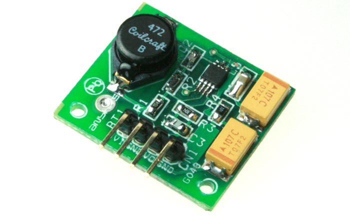
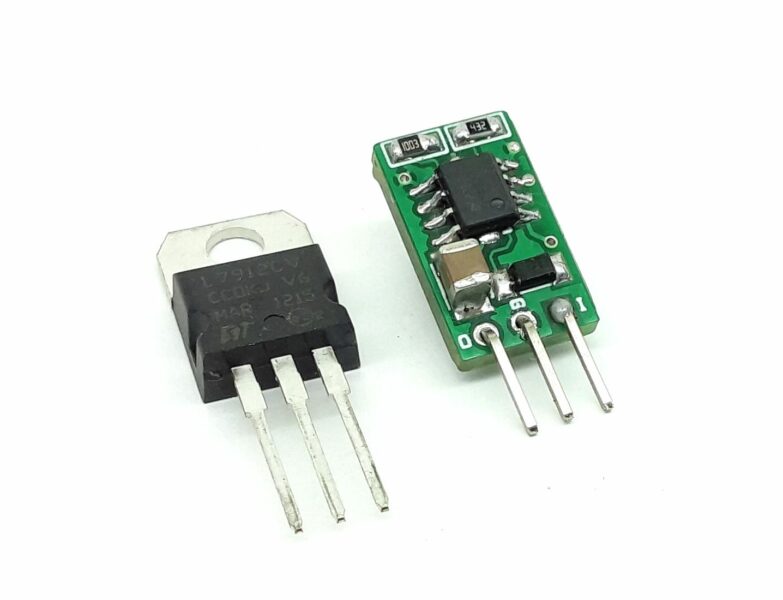
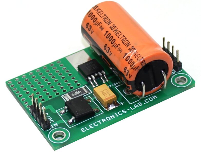
This project is a step up DC to DC power converter able to convert 2.4V – 5V to 5Vdc.
Description
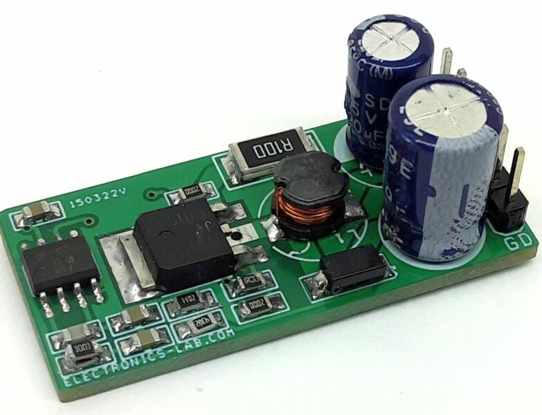
This project has been designed around Texas Instruments LM2623 IC, The LM2623 is a high efficiency, general purpose step-up DC-DC switching regulator for battery powered and low input voltage systems. It accepts an input voltage between 2.4V to 12V volts and converts it into 5V DC. Efficiencies up to 90% are achievable with the LM2623.
Features:
- Good Efficiency over a very wide load range
- Very low output voltage ripple
- 2.4V to 5V (Possible Input Supply up to 14V operating voltage)
- 5V output voltage (Other output voltages possible by changing R3 and R4)
- 600mA output current
Application:
- Hand held instruments
- Cameras, PDA, Cellphones
- White LED driver
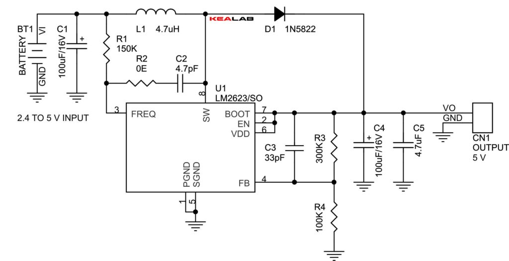
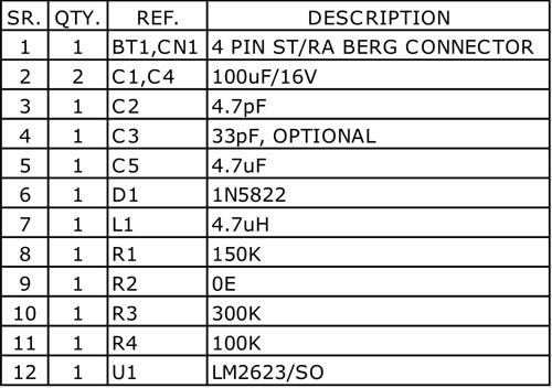
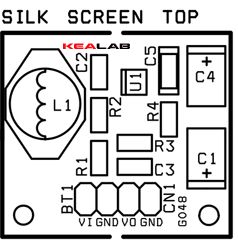
Schematic




I like electronics lab.com
Thanks for visiting!
Does it provide 5V continously even when the input is 2.5V ?
Sure, input can be in the range of 2.4 – 12V
will the output be stable if the Vin fluctuates?
That’s the purpose of this voltage converter. Keep in mind that the voltage should be inside the input limits.
Sorry, i am really zero knowledge of this, and i dont know where to start learning. can i ask how much R3 and R4 should be for output around 3.3v-3.5v. thanx if you want share how to calculate it. 🙂
I can’t enter the equation here. Please check on datasheet page 11 – chapter 8.2.2.3 Setting the Output Voltage. http://www.ti.com.cn/cn/lit/ds/symlink/lm2623.pdf A value of 50k to 100k is suggested for R4. Then, R3 can be selected using Equation 1.
yes, i see.. thanx for the link and reference page number..:) so if R4 is 100k, i just need R3 150-160K.. really thanks…
What kind of inductor you used here and what is R2 0E?
Please check this inductor: http://gr.mouser.com/ProductDetail/Coilcraft/DO3316P-472MLD/?qs=sGAEpiMZZMsg%252by3WlYCkU2kWFds1hA9DyIvtLqsAU1Q%3d
R2 it’s a zero Ohm resistor
Can i use this inductor? https://www.amazon.com/uxcell-Axial-4-7uH-Color-Inductors/dp/B008MP0HS0. Can i ask the C5 too? Can i use a through hole capacitor? Thanks
No, you will need a high power inductor like the one on the mouser.com link above. As for C5 you can use a through hole capacitor that will be fitted on the PCB.
Can you recommend an alternative inductor that is not surface mounted because i need it for my project and we need to put it on breadboard. Thank you so much 🙂
You may try an inductor like this: http://gr.mouser.com/ProductDetail/Bourns/RLB9012-4R7ML/?qs=sGAEpiMZZMsg%252by3WlYCkU1ozaMmf%252bSo4%2feNymmEonLM%3d
http://ph.rs-online.com/web/p/leaded-inductors/6755131/ this one?
It should work.
can i use electrolytic capacitor on C5?
How about using a 1.5V or 6V battery for the input?
can i use a polarize capacitor for C5?
It’s better to use a ceramic capacitor there.
Can i use solar panel that’s 3V for the input instead of a battery?
You may use a solar panel on the input that is able to provide 2.4 to 12V output.
Hi! When i finished breadboarding the circuit and put an input voltage of 6 volts the output was 6 volts too. Why does it happened? 🙁
Please try a lower input voltage at the range of 2.4-4.5V to check if the regulator converts it to 5V
Hi 🙂 I changed the input into 3V but the output is 3V too.
Please check for damaged diode or IC.
what is the output A’s
max output current is 600mA
What are the exact dimensions of the pcb drawn in this page. Thanks.
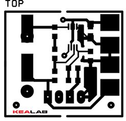
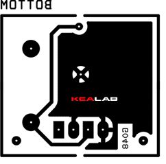
PCB dimensions are 24.13 x 26.99mm
Can i use through hole components (on a new pcb) for all the parts (except the lm2623 of course) ?
Sure, it will work just fine.
Thanks for answering.
Another issue : is there a way to improve the maximum output current to let’s say 1.5A or 2A. What are the modifications needed for this purpose? Thanks in advance.
For that output current, you probably need a completely new design with different IC.
PCB Size 24.13X26.99MM
Thanks
Why the output is oscillating continuously between 4.8 and 5.3 V (not stable) ?
Have you placed all filtering capacitors to the output?
Have rebuilt the circuit using your pcb (not the mine) and it works just fine. I’m using it to feed an audio amplifier rated at 6w (2x3w) so the current drawn is 1.2A (6w/5v) vs an announced nominal current of 500mA ?? Is there an explanantion.
Thanks.
6W should be the maximum instantaneous power delivered to the speakers and not RMS power which is lower. So that’s why your amplifier has 500mA nominal current.
where can I buy the components for this board?
Your can source the parts online from various suppliers, like mouser.com ebay.com and others.
Hi i need to charge my samsung s8 with this kind of circuit via aa batteries. .So in need 2 A output. Are there any suggestion for me?
where i can buy the module? .. but if input 2.4 volt and current is 30 micro ampere, can work the module?
Hi Kumar,
could you send me the gerber file?
@ andrea-poma@hotmail.com
Thanks
I’ve just uploaded the Gerber files for this project on the downloads section above.
i need
@ 1-5 vdc to 5 vdc dc dc step up converter with 2000ma
@ intelligent emergency led light driver making circuit diagram . 230vac input and 4vdc utput. 3,7 or 4 vdc li ion battery back up.
ii want t make by myself. i need easy diagram with available parts.
For 1. you will need a completely new IC and design, we don’t have such board. 2. We only have an emergency light with Lead Acid battery backup.
Hi. Please help me out here
My challenge: I need to boost 3V to 5V, and I need to do it yesterday. – I need something I can buy fast.
Can I buy 10 pcs of this or something smilair and where?
Perferably in Denmark, Europe, US, Asia – This due to the delivery time.
VERY big thanks for any help.
Dennis Jensen
Hi, thanks for your interest on this board. We can produce this for you on order but we will need at least 2 weeks time. Let me know if this works for you. We are based in EU.
Can i get 5v from 10v for this circuit?If not ,what are the modification?