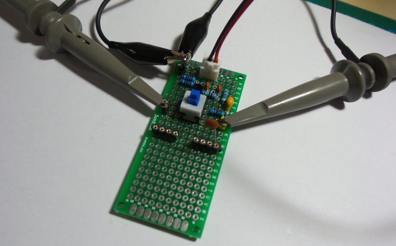
Stoneslice has shared a Curve Tracer tutorial on Youtube that uses an X Y mode Oscilloscope to test components and their characteristics. Using the on-board Phase Shift Oscillator to provide the test signal, passive and active parts can be tested.
These are the components needed to build the project:
- 1 x NPN Switching Transistor
- 1 x 1K Resistor
- 1 x 4.7K Resistor
- 1 x 8.2K Resistor
- 2 x 10K Resistor
- 1 x 2M Resistor
- 3 x 4.7nF Capacitor
- 1 x 1uF Electrolytic Capacitor
- 1 x DPDT Switch
- 4 x Sockets
- 4 x Test points
In this video Stoneslice demonstrates the project sharing all the technical details and information needed, check it out:
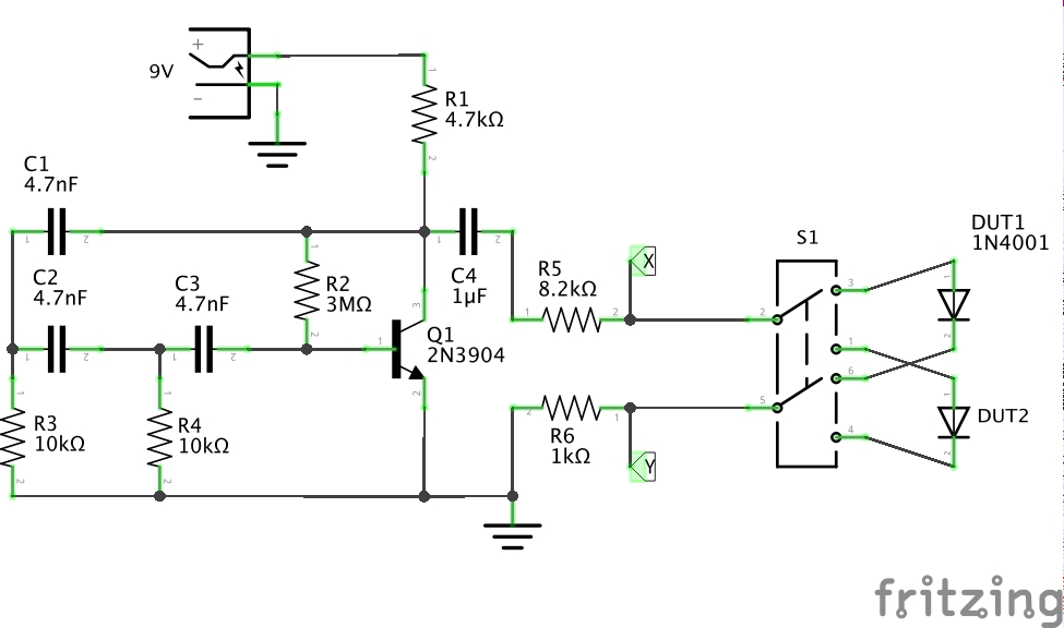
Inspired by Stoneslice’s tutorial, Paul Gallagher (tardate) has developed further on the Curve Tracer by using a simple DC Powered oscillator to drive a test signal across the device under test, instead of relying on an AC power supply. Paul also added a DPDT switch to toggle and compare two devices under test.
X-Y signals are plotted on an oscilloscope to visualise the characteristic curve for the component.
- X is the ground-referenced voltage at the anode of the device under test (DUT)
- Y is the voltage across the resistor at the cathode of the DUT, which is proportional to the current flowing through the DUT.
Paul tested multiple components like resistors, diodes and capacitors demonstrating the charging and discharging cycles.
Below is the schematics of Paul’s circuit.
Paul has launched LittleArduinoProjects series, a collection of electronics projects often involving an Arduino, and this project’s number is 245! Check his two technical blogs: LittleArduinoProjects, and LittleCodingKata – where he tests tools and talks about software development topics.
Further details about this Curve Tracer are available at Github, where you can find schematic, detailed tutorials, the project snapshots in action and resources.






there is no ramp generator for transistor? Also, just a 5volt AC transformer with 1K or 10K resistor is enough to measure diode curve